Adjustment and Maintenance
4
pass through the first pinhole and then use the second mirror (#2) to adjust
the beam angle so that it passes through the second (furthest) pinhole. This
procedure may require several iterations to get the alignment perfect.
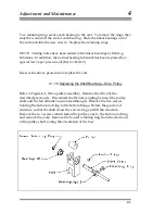
Figure 4-2
Beam expander with alignment pinholes mounted
4.2.2.6.Beam Expander
4.2.2.6.1.Focusing lens:
Remove the alignment pinholes and put the focusing lens (25.4 mm focal
length) into the first lens holder. The lens should be inserted so that curved
surface is towards the input beam (Figure 4-3).
4-11
Summary of Contents for FG5
Page 22: ...Design Components and Function 2 Figure 2 10 The Superspring 2 14 ...
Page 31: ...Design Components and Function 2 Figure 2 13 Rotation Monitor 2 23 ...
Page 32: ......
Page 42: ...How to Set Up and Run the FG5 3 3 10 ...
Page 44: ...How to Set Up and Run the FG5 3 Figure 3 2 V Post 3 12 ...
Page 53: ...How to Set Up and Run the FG5 3 1 Backup the data 2 Shut off computer power 3 21 ...
Page 87: ...Adjustment and Maintenance 4 4 29 ...
Page 91: ...Adjustment and Maintenance 4 4 33 ...
Page 104: ...Troubleshooting 5 5 2 ...
Page 117: ...Troubleshooting 5 5 15 ...
Page 131: ...Checklists and Logs Appendix D 9 3 ...
Page 140: ...Checklists and Logs Appendix D Table 9 6 Replacing Drive Belt 9 12 ...
Page 145: ...Checklists and Logs Appendix D Table 9 10 Replace Linear Bearings 9 17 ...
Page 149: ...Checklists and Logs Appendix D Table 9 13 Replace Shaft Encoder 9 21 ...


