Adjustment and Maintenance
4
29
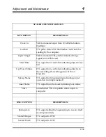
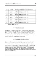
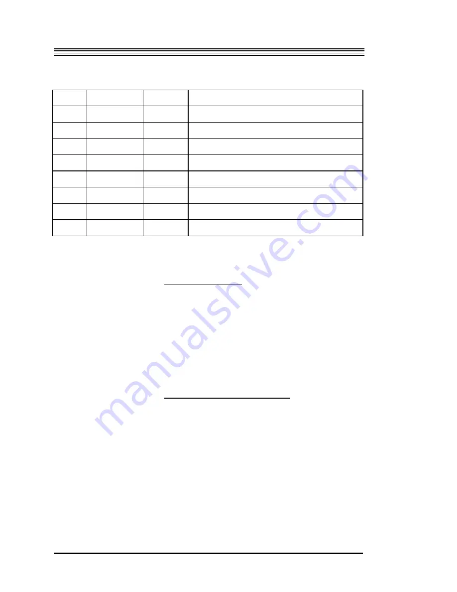
LATCH
output (extended) "latch" signal to computer
30
DL7
output latched clock count, bit 7
31
DL6
output latched clock count, bit 6
32
DL5
output latched clock count, bit 5
33
DL4
output latched clock count, bit 4
34
DL3
output latched clock count, bit 3
35
DL2
output latched clock count, bit 2
36
DL1
output latched clock count, bit 1
37
DL0
output latched clock count, bit 0
Table 4-3 DB37 Connector
4.4.1.4.Rubidium Oscillator
The FG5 uses a rubidium oscillator as a frequency standard (atomic clock).
The oscillator generates a 10-MHz sine wave with amplitude of .5Vrms into
50
Ω
. It is used by the UTIC and scaler-counter to provide accurate time
information. The oscillator is split by a 50
Ω
POWER
splitter. From there, the
clock is sent into the 10-MHz IN BNC on the back of the UTIC and also into
the Clock In BNC on the back of the scaler counter.
4.4.1.5.Universal Time Interval Counter
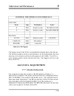
To measure the time between a scaled fringe and the next scaled clock, the
FG5 uses a Universal Time Interval Counter (UTIC). The scaler-counter
SCALED FRINGES signal is connected to the front A input of the UTIC,
while SCALED CLOCKS signal is connected to the B input. After each time
interval is measured, the UTIC generates a LATCH signal from a rear BNC.
The LATCH signal is connected to the Scaler/Counter where it is used to
latch the clock and fringe number onto the output pins of the parallel I/O
port of the Scaler/Counter. The UTIC is controlled and read by the computer
through an IEEE-488 cable.
4-32
Summary of Contents for FG5
Page 22: ...Design Components and Function 2 Figure 2 10 The Superspring 2 14 ...
Page 31: ...Design Components and Function 2 Figure 2 13 Rotation Monitor 2 23 ...
Page 32: ......
Page 42: ...How to Set Up and Run the FG5 3 3 10 ...
Page 44: ...How to Set Up and Run the FG5 3 Figure 3 2 V Post 3 12 ...
Page 53: ...How to Set Up and Run the FG5 3 1 Backup the data 2 Shut off computer power 3 21 ...
Page 87: ...Adjustment and Maintenance 4 4 29 ...
Page 91: ...Adjustment and Maintenance 4 4 33 ...
Page 104: ...Troubleshooting 5 5 2 ...
Page 117: ...Troubleshooting 5 5 15 ...
Page 131: ...Checklists and Logs Appendix D 9 3 ...
Page 140: ...Checklists and Logs Appendix D Table 9 6 Replacing Drive Belt 9 12 ...
Page 145: ...Checklists and Logs Appendix D Table 9 10 Replace Linear Bearings 9 17 ...
Page 149: ...Checklists and Logs Appendix D Table 9 13 Replace Shaft Encoder 9 21 ...


