12
| POWER PACK SERVICE MANUAL
MICROMATIC.COM | 866-327-4159
REPLACING MOTOR
(MMPP4301-EP, MMPP4301, MMPP4301-WC, MMPP4301-PKG, MMPP4301-PKG-WC, MMPP4302, MMPP4302-WC,
MMPP4302-PKG, MMPP4302-PKG-WC, MMPP4303-PKG, MMPP4303-PKG-WC, MMPP4303-PKG-3, MMPP4305-PKG,
MMPP4305-PKG-WC, MMPP4305-PKG-3, MMPP4305-PKG-WC3, MMPP4307-PKG, MMPP4307-PKG-WC,
MMPP4307-PKG-3, MMPP4307-PKG-3-WC, MMPP4307-PKG-4, MPP4307-PKG-4-WC)
Note: Replacement motor is not supplied with electrical cord. Remove and reuse cord from defective motor.
1. Unplug unit from receptacle.
2. Support pump and loosen clamp holding pump to motor. As clamp is loosed pump will eventually
disconnect from motor. Make sure pump does not damage glycol supply line as it becomes free from motor.
3. With pump free from motor remove drive key and replace.
4. While supporting motor remove four (4) nuts and hardware from mounting studs.
5. Mount new motor by aligning mounting bracket with mounting studs and reattaching mounting nuts and
hardware.
Note: new motor is supplied with mounting bracket.
6. Reattach pump to motor with clamp making sure new drive key aligns with motor shaft.
7. Locate defective motor and remove electrical connection cover plate (follow cord to where it enters back
of motor) exposing cord connections. Remove ground connection by unscrewing green screw and
removing ground wire. Unplug remaining 2 wires by pulling firmly on connections. Reattach cord to new
motor by affixing ground wire to green ground screw and plugging 2 wires to motor connections. Place
cord in electrical wire channel in motor housing and reattach electrical connection cover plate.
8. Plug cord into receptacle.
REPLACING THERMOSTAT IN ALL UNITS
1. Unplug unit from receptacle.
2. Remove the screws holding the thermostat housing to the unit. Slide the white plastic brackets
backwards off of the thermostat. Remove thermostat from housing.
3. Making note of which wire is connected to which number on the thermostat, remove wires using small
slotted screwdriver. Reattach wires to correct numbers on new thermostat and reassemble into housing.
NOTE: All XR02 thermostats are supplied with a four wire connector. If the unit has an old XR20
thermostat, connect the 120v supply wires that were on terminals 7 and 8 to the harness wires coming
from terminals 6 and 7 on the new XR02. The wires that were connected to terminals 4 and 5 on the old
thermostat should connect to the harness wires coming from terminals 8 and 9.
4. Reattach thermostat housing to unit and plug unit into receptacle.
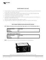
5. For thermostat setting instructions see page 7.
REWIRING A DANFOSS THERMOSTAT INTO A CONTROL BOX
WITH A DIXELL THERMOSTAT
1. Cut the black, white, red and yellow wires from the old harness on the Dixell thermostat.
2. Attach the yellow wire from the Danfoss thermostat to the yellow wire from the harness.
3. Attach the white wire from the Danfoss thermostat to the white wire from the harness.
4. Attach the black wire from the Danfoss thermostat to the black and red wires from the harness.
Summary of Contents for MMPP4301
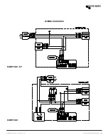
Page 15: ...MICROMATIC COM 866 327 4159 POWER PACK SERVICE MANUAL 15 WIRING DIAGRAMS MMPP4301 EP MMPP4301 ...
Page 16: ...16 POWER PACK SERVICE MANUAL MICROMATIC COM 866 327 4159 MMPP4301 PKG MMPP4302 ...
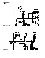
Page 17: ...MICROMATIC COM 866 327 4159 POWER PACK SERVICE MANUAL 17 MMPP4302 PKG MMPP4303 PKG ...
Page 18: ...18 POWER PACK SERVICE MANUAL MICROMATIC COM 866 327 4159 MMPP4303 PKG 3 MMPP4305 PKG ...
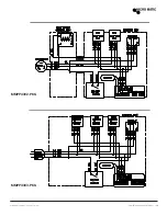
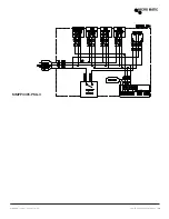
Page 19: ...MICROMATIC COM 866 327 4159 POWER PACK SERVICE MANUAL 19 MMPP4305 PKG 3 ...
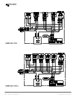
Page 20: ...20 POWER PACK SERVICE MANUAL MICROMATIC COM 866 327 4159 MMPP4307 PKG MMPP4307 PKG 3 ...
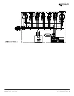
Page 21: ...MICROMATIC COM 866 327 4159 POWER PACK SERVICE MANUAL 21 MMPP4307 PKG 4 ...
Page 22: ...22 POWER PACK SERVICE MANUAL MICROMATIC COM 866 327 4159 ...

