iv
Micro Motion
®
Model 2200S Transmitters
Contents
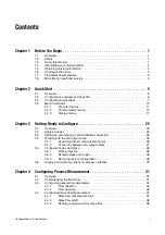
10.8
Fault conditions . . . . . . . . . . . . . . . . . . . . . . . . . . . . . . . . . . . . . . . . . . . . . . . . . . . . 105
10.9
HART output problems . . . . . . . . . . . . . . . . . . . . . . . . . . . . . . . . . . . . . . . . . . . . . . 105
10.10
I/O problems . . . . . . . . . . . . . . . . . . . . . . . . . . . . . . . . . . . . . . . . . . . . . . . . . . . . . . 106
10.11
Sensor simulation mode . . . . . . . . . . . . . . . . . . . . . . . . . . . . . . . . . . . . . . . . . . . . . 107
10.12
Status alarms . . . . . . . . . . . . . . . . . . . . . . . . . . . . . . . . . . . . . . . . . . . . . . . . . . . . . 107
10.13
Checking process variables . . . . . . . . . . . . . . . . . . . . . . . . . . . . . . . . . . . . . . . . . . 110
10.14
Diagnosing wiring problems . . . . . . . . . . . . . . . . . . . . . . . . . . . . . . . . . . . . . . . . . . 113
10.14.1
Checking the power supply wiring . . . . . . . . . . . . . . . . . . . . . . . . . . . . . 113
10.14.2
Checking grounding. . . . . . . . . . . . . . . . . . . . . . . . . . . . . . . . . . . . . . . . 113
10.14.3
Checking the HART communication loop . . . . . . . . . . . . . . . . . . . . . . . 113
10.15
Checking the communication device. . . . . . . . . . . . . . . . . . . . . . . . . . . . . . . . . . . . 113
10.16
Checking the output wiring and receiving device . . . . . . . . . . . . . . . . . . . . . . . . . . 114
10.17
Checking slug flow . . . . . . . . . . . . . . . . . . . . . . . . . . . . . . . . . . . . . . . . . . . . . . . . . 114
10.18
Checking output saturation . . . . . . . . . . . . . . . . . . . . . . . . . . . . . . . . . . . . . . . . . . . 115
10.19
Checking the HART address and Loop Current Mode parameter . . . . . . . . . . . . . 115
10.20
Checking the flow measurement configuration . . . . . . . . . . . . . . . . . . . . . . . . . . . . 115
10.21
Checking the characterization. . . . . . . . . . . . . . . . . . . . . . . . . . . . . . . . . . . . . . . . . 115
10.22
Checking the calibration . . . . . . . . . . . . . . . . . . . . . . . . . . . . . . . . . . . . . . . . . . . . . 116
10.23
Checking the test points . . . . . . . . . . . . . . . . . . . . . . . . . . . . . . . . . . . . . . . . . . . . . 116
10.23.1
Obtaining the test points . . . . . . . . . . . . . . . . . . . . . . . . . . . . . . . . . . . . 116
10.23.2
Drive gain problems. . . . . . . . . . . . . . . . . . . . . . . . . . . . . . . . . . . . . . . . 116
10.23.3
Low pickoff voltage . . . . . . . . . . . . . . . . . . . . . . . . . . . . . . . . . . . . . . . . 117
10.24
Checking sensor circuitry . . . . . . . . . . . . . . . . . . . . . . . . . . . . . . . . . . . . . . . . . . . . 117
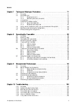
Appendix A Default Values and Ranges . . . . . . . . . . . . . . . . . . . . . . . . . . . . 123
A.1
Overview . . . . . . . . . . . . . . . . . . . . . . . . . . . . . . . . . . . . . . . . . . . . . . . . . . . . . . . . . 123
A.2
Most frequently used defaults and ranges . . . . . . . . . . . . . . . . . . . . . . . . . . . . . . . 123
Appendix B Flowmeter Installation Types and Components. . . . . . . . . . . . . . . 127
B.1
Overview . . . . . . . . . . . . . . . . . . . . . . . . . . . . . . . . . . . . . . . . . . . . . . . . . . . . . . . . . 127
B.2
Transmitter components . . . . . . . . . . . . . . . . . . . . . . . . . . . . . . . . . . . . . . . . . . . . . 127
B.3
Terminal diagrams. . . . . . . . . . . . . . . . . . . . . . . . . . . . . . . . . . . . . . . . . . . . . . . . . . 128
Appendix C Model 2200S Display and User Interface . . . . . . . . . . . . . . . . . . . 129
C.1
Overview . . . . . . . . . . . . . . . . . . . . . . . . . . . . . . . . . . . . . . . . . . . . . . . . . . . . . . . . . 129
C.2
Identifying the components of the user interface . . . . . . . . . . . . . . . . . . . . . . . . . . 129
C.3
Removing and replacing the transmitter housing cover . . . . . . . . . . . . . . . . . . . . . 130
C.4
Using the display, the buttons, and the display menu system . . . . . . . . . . . . . . . . . 130
C.4.1
Accessing the display menu system . . . . . . . . . . . . . . . . . . . . . . . . . . . 130
C.4.2
Entering floating-point values from the display menus . . . . . . . . . . . . . 131
C.5
Codes and abbreviations . . . . . . . . . . . . . . . . . . . . . . . . . . . . . . . . . . . . . . . . . . . . 133
Appendix D Connecting with ProLink II Software . . . . . . . . . . . . . . . . . . . . . . 135
D.1
Overview . . . . . . . . . . . . . . . . . . . . . . . . . . . . . . . . . . . . . . . . . . . . . . . . . . . . . . . . . 135
D.2
Requirements . . . . . . . . . . . . . . . . . . . . . . . . . . . . . . . . . . . . . . . . . . . . . . . . . . . . . 135
D.3
Configuration upload/download . . . . . . . . . . . . . . . . . . . . . . . . . . . . . . . . . . . . . . . 135
D.4
Connecting from a PC to a Model 2200S transmitter . . . . . . . . . . . . . . . . . . . . . . . 135
D.5
ProLink II language . . . . . . . . . . . . . . . . . . . . . . . . . . . . . . . . . . . . . . . . . . . . . . . . . 138
Summary of Contents for 2200S
Page 8: ...vi Micro Motion Model 2200S Transmitters ...
Page 12: ...4 Micro Motion Model 2200S Transmitters ...
Page 32: ...24 Micro Motion Model 2200S Transmitters ...
Page 38: ...30 Micro Motion Model 2200S Transmitters ...
Page 68: ...60 Micro Motion Model 2200S Transmitters ...
Page 92: ...84 Micro Motion Model 2200S Transmitters ...
Page 102: ...94 Micro Motion Model 2200S Transmitters ...
Page 110: ...102 Micro Motion Model 2200S Transmitters ...
Page 130: ...122 Micro Motion Model 2200S Transmitters ...
Page 134: ...126 Micro Motion Model 2200S Transmitters ...
Page 150: ...142 Micro Motion Model 2200S Transmitters ...
Page 156: ...148 Micro Motion Model 2200S Transmitters ...
Page 157: ......


