82
Micro Motion
®
Model 2200S Transmitters
Testing and Moving to Production
7.5
Using sensor simulation to test, tune, and troubleshoot the system
Sensor simulation allows you to tell the transmitter to behave as if it were receiving specific values for
mass flow, temperature, and density from the sensor. You can use sensor simulation for a variety of
purposes:
•
Testing and verifying the flowmeter’s response to a variety of process conditions without
having to create those conditions in the real world.
•
Analyzing the system’s response to various process conditions.
•
Tuning the loop.
•
Locating problems. For example, signal oscillation or noise is a common occurrence. The
source could be the PLC, the meter, improper grounding, or a number of other factors. By
setting up simulation to output a flat signal, then checking the signal at various points between
the transmitter and the receiving device, you can determine the point at which the noise is
introduced.
When sensor simulation is enabled, it affects all analog and digital outputs, and therefore affects all
calculations that include these values. It does not change any diagnostic values.
CAUTION!
Be sure
that your process is prepared to handle the consequences of your simulation setup.
To set up sensor simulation
,
follow the steps below:
1. If you are using:
•
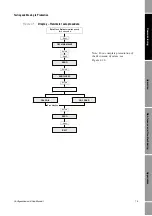
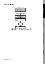
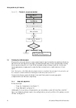
The Communicator, refer to Figure 2-9.
•
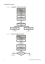
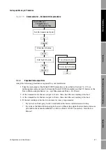
ProLink II, refer to Figure 2-4.
2. Enable sensor simulation mode.
3. For mass flow:
a.
Specify the type of simulation you want: fixed value, triangular wave, or sine wave.
b.
Enter the required values.
•
If you specified fixed value simulation, enter a fixed value.
•
If you specified triangular wave or sine wave simulation, enter a minimum amplitude,
maximum amplitude, and period.
4. Repeat Step 3 for temperature and density.
Be sure to disable simulation mode when the tests are complete.
7.6
Backing up and restoring the configuration
If you are using ProLink II, you can copy the configuration dataset to a file on your PC. The
configuration dataset can be restored from the PC to the transmitter if required.
To copy the configuration dataset to a file on your PC:
1. Connect to the transmitter using ProLink II.
2. Select
File > Load from Xmtr to File
.
3. Specify the name and location of the backup file.
To restore the configuration dataset:
1. Connect to the transmitter using ProLink II.
2. Select
File > Send to Xmtr from File
.
3. Specify the name and location of the backup file.
Summary of Contents for 2200S
Page 8: ...vi Micro Motion Model 2200S Transmitters ...
Page 12: ...4 Micro Motion Model 2200S Transmitters ...
Page 32: ...24 Micro Motion Model 2200S Transmitters ...
Page 38: ...30 Micro Motion Model 2200S Transmitters ...
Page 68: ...60 Micro Motion Model 2200S Transmitters ...
Page 92: ...84 Micro Motion Model 2200S Transmitters ...
Page 102: ...94 Micro Motion Model 2200S Transmitters ...
Page 110: ...102 Micro Motion Model 2200S Transmitters ...
Page 130: ...122 Micro Motion Model 2200S Transmitters ...
Page 134: ...126 Micro Motion Model 2200S Transmitters ...
Page 150: ...142 Micro Motion Model 2200S Transmitters ...
Page 156: ...148 Micro Motion Model 2200S Transmitters ...
Page 157: ......


