RFT9709 Transmitter Instruction Manual
15
Wiring
continued
Wirin
g
Sta
rt
up
T
roub
lesh
ootin
g
Bef
o
re
Y
ou Be
gin
Mou
n
ting
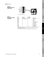
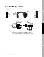
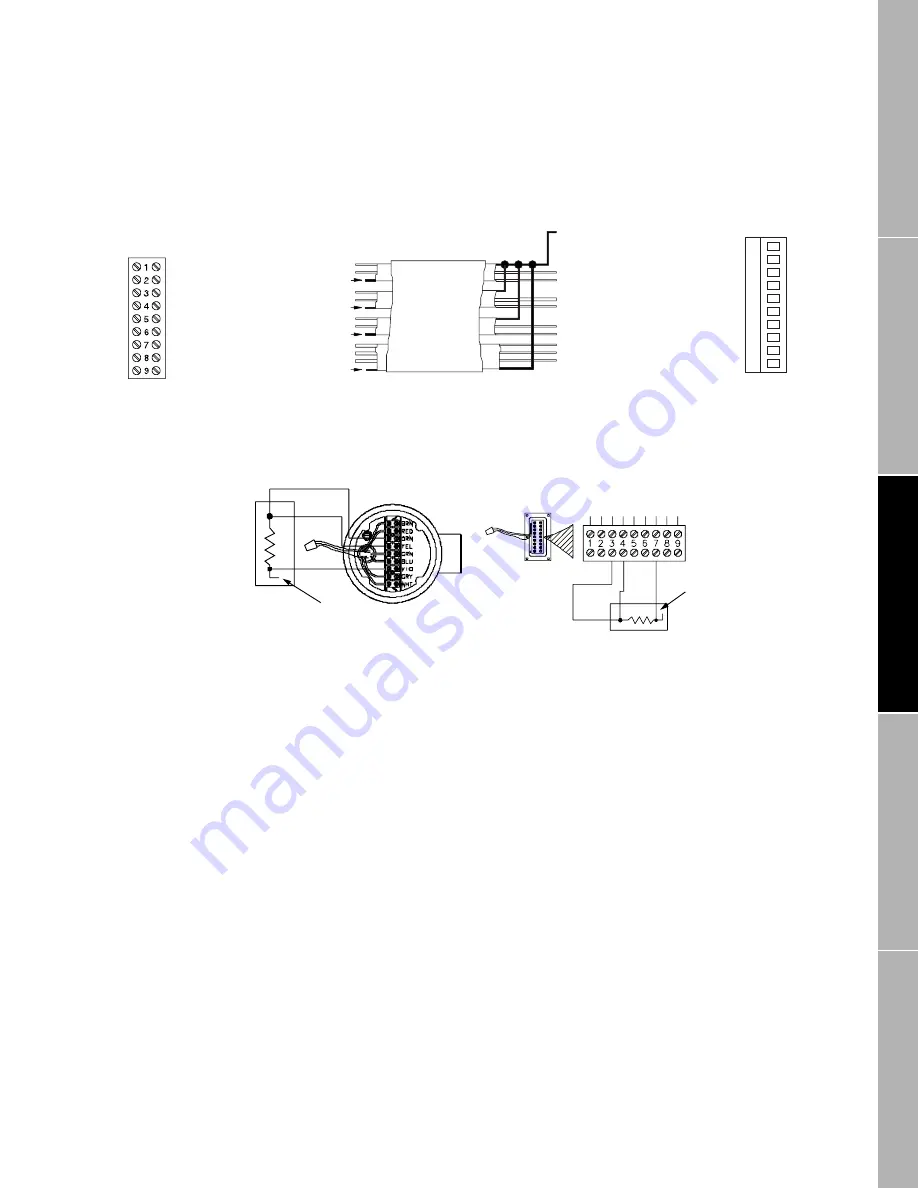
Figure 2-7. Wiring to BASIS
®
F, Model D, and DL sensors
0
1
2
3
4
5
6
7
8
9
Brown
Red
Clip drain wire back
Green
White
Clip drain wire back
Blue
Gray
Clip drain wire back
Orange
Violet
Yellow
Clip drain wire back
BASIS
®
, Model D
or DL sensor
terminals
Flowmeter
cable
Brown
Red
Green
White
Blue
Gray
Orange
Violet
Yellow
Black
(Drains from all
wire sets)
Maximum cable length 1000 ft. (300 m)
RFT9709
terminals
No connection
BASIS
®
, Model D or DL
sensor terminals
No connection
D600 sensor
terminals
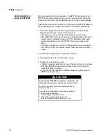
1. In the sensor junction box, identify the violet, yellow, and orange wires that come from inside the sensor.
2. Disconnect these wires from the terminal block, then tie all three together with a wire nut to protect
exposed wire ends.
3. Connect three wires from the external RTD to the terminals from Step 2, as illustrated above. If the RTD
has a fourth wire, it remains unconnected.
Optional remote temperature detector (RTD) wiring (required for API)
3-wire or 4-wire
RTD
3-wire or 4-wire
RTD
Br
o
w
n
Re
d
O
ra
nge
Y
e
llo
w
G
reen
Blu
e
V
iol
et
Gr
a
y
Wh
it
e
Black (drains)
Brown
Red
Orange
Yellow
Green
Blue
Violet
Gray
White
Brown
Red
Orange
Yellow
Green
Blue
Violet
Gray
White
09wire.fm Page 15 Monday, March 1, 1999 4:31 PM
Summary of Contents for Fisher-Rosemount RFT9709
Page 1: ...Model RFT9709 Transmitter Instruction Manual March 1999 ...
Page 2: ......
Page 4: ......
Page 8: ...iv RFT9709 Transmitter Instruction Manual ...
Page 34: ...26 RFT9709 Transmitter Instruction Manual ...
Page 52: ...44 RFT9709 Transmitter Instruction Manual ...
Page 60: ...52 RFT9709 Transmitter Instruction Manual ...
Page 62: ...54 RFT9709 Transmitter Instruction Manual ...
Page 72: ...64 RFT9709 Transmitter Instruction Manual ...
Page 73: ......

