RFT9709 Transmitter Instruction Manual
19
Wiring
continued
Wirin
g
Sta
rt
up
T
roub
lesh
ootin
g
Bef
o
re
Y
ou Be
gin
Mou
n
ting
HART multidrop network
wiring
The Bell 202 physical layer is used for digital communication with the
HART protocol. Devices in a HART multidrop network communicate by
sending and receiving signals to and from one another.
Up to 15 transmitters can be connected using the Bell 202 standard.
Other Rosemount
®
SMART FAMILY
®
transmitters can also participate in
a HART network.
• Using multiple transmitters in a HART network requires assigning a
unique address from 1 to 15 to each transmitter. Assigning an address
of 1 to 15 to the RFT9709 causes the primary mA output to remain at a
constant 4 mA level.
• A HART-compatible control system can communicate with any device
in a HART network over the same 2-wire pair.
Configuration switches on the RFT9709 allow the choice of Bell 202 or
RS-485 physical layers for HART or Modbus
®
communications. Make
sure switches are set as instructed in Section C.2, page 47, before
attempting to use the RFT9709 in a HART multidrop network.
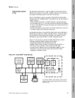
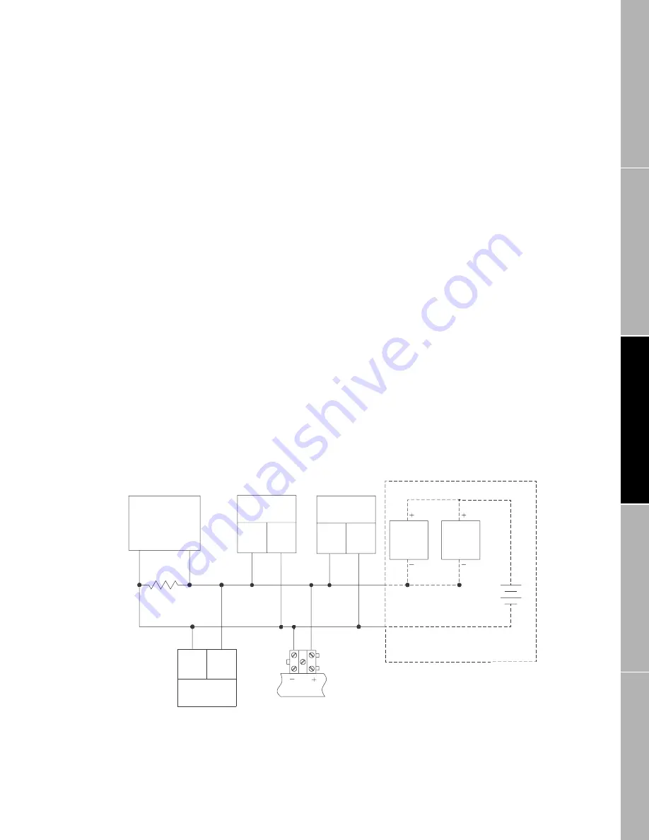
Figure 2-11 shows how to connect multiple transmitters to a host
controller for Bell 202 HART digital communication.
• The Bell 202 standard requires twisted-pair wire.
• SMART FAMILY devices require a minimum loop resistance of
250 ohms. Loop resistance must not exceed 1000 ohms.
• Connect the mA outputs from each transmitter together so they
terminate at a common load resistor, with at least 250 ohms
impedance, installed in series.
Figure 2-11. Typical HART
®
network wiring
PV+
17
PV–
18
PV+
CN2-
Z30
PV–
CN2-
D30
4-20mA
24
DC
PV+
11
PV–
12
For optimum HART communication, make sure the
output loop is single-point grounded to instrument
grade ground.
ProLink
®
PC Interface
(Bell 202)
RFT9739
field-mount
RFT9739
rack-mount
SMART
FAMILY
®
trans-
mitter
SMART
FAMILY
trans-
mitter
DC source required for
other HART
®
4-20 mA
passive transmitters
RFT9709
IFT9701
Resistor
(250 ohm
load)
09wire.fm Page 19 Monday, March 1, 1999 4:31 PM
Summary of Contents for Fisher-Rosemount RFT9709
Page 1: ...Model RFT9709 Transmitter Instruction Manual March 1999 ...
Page 2: ......
Page 4: ......
Page 8: ...iv RFT9709 Transmitter Instruction Manual ...
Page 34: ...26 RFT9709 Transmitter Instruction Manual ...
Page 52: ...44 RFT9709 Transmitter Instruction Manual ...
Page 60: ...52 RFT9709 Transmitter Instruction Manual ...
Page 62: ...54 RFT9709 Transmitter Instruction Manual ...
Page 72: ...64 RFT9709 Transmitter Instruction Manual ...
Page 73: ......


