RFT9709 Transmitter Instruction Manual
25
Wiring
continued
Wiring instructions
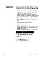
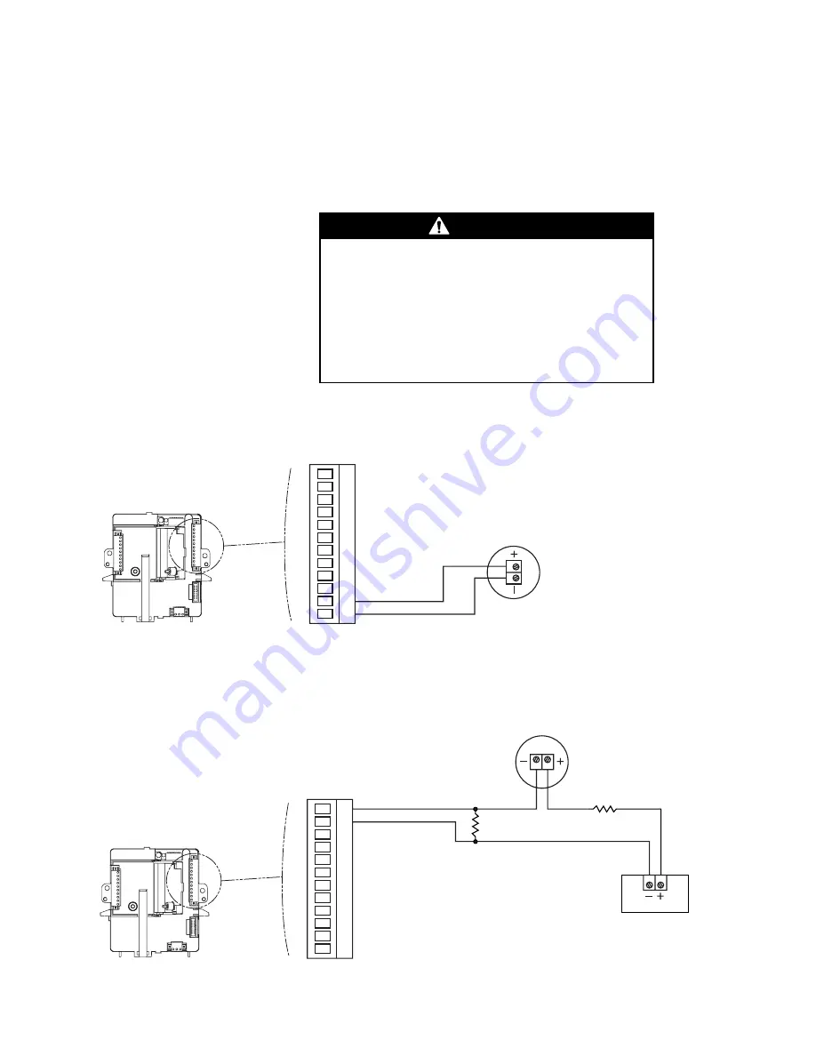
Instructions for wiring the RFT9709 to a pressure transmitter are
provided below.
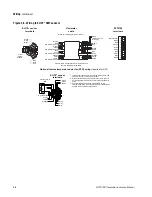
• Use Figure 2-16a for an internally powered configuration.
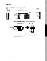
• Use Figure 2-16b for an externally powered (multidrop) configuration.
Figure 2-16a. Pressure transmitter wiring, internally powered
Figure 2-16b. Pressure transmitter wiring, externally powered (multidrop network)
WARNING
Failure to comply with requirements for intrinsic
safety in a hazardous area could result in an
explosion.
Pressure transmitter wiring is not intrinsically safe.
Keep pressure transmitter wiring separated from
power-supply wiring, intrinsically safe sensor wiring, and
any other intrinsically safe wiring.
Pressure transmitter
SMART only
(1151 or 3051)
RFT9709 terminals
for output wiring
11 12
13 1
4
15 1
6
17 1
8
19
20
21 22
VF+/DP+
(signal line)
DP– (return)
Pressure transmitter
SMART only (1151 or 3051)
RFT9709 terminals
for output wiring
PV+ (signal line)
PV– (return)
11 12
13 1
4
15 1
6
17 1
8
19
20 21
22
250 ohm ±5%
0.5 W
250 ohm ±5%
0.5 W
Power
supply
24 VDC
09wire.fm Page 25 Monday, March 1, 1999 4:31 PM
Summary of Contents for Fisher-Rosemount RFT9709
Page 1: ...Model RFT9709 Transmitter Instruction Manual March 1999 ...
Page 2: ......
Page 4: ......
Page 8: ...iv RFT9709 Transmitter Instruction Manual ...
Page 34: ...26 RFT9709 Transmitter Instruction Manual ...
Page 52: ...44 RFT9709 Transmitter Instruction Manual ...
Page 60: ...52 RFT9709 Transmitter Instruction Manual ...
Page 62: ...54 RFT9709 Transmitter Instruction Manual ...
Page 72: ...64 RFT9709 Transmitter Instruction Manual ...
Page 73: ......


