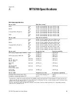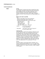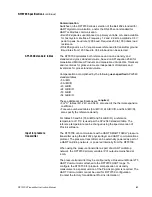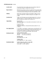
RFT9709 Transmitter Instruction Manual
27
Wirin
g
Sta
rt
up
T
roub
lesh
ootin
g
Bef
o
re
Y
ou Be
gin
Mou
n
ting
Installation
Step 3
Startup
3.1
Initialization
After wiring has been connected, power can be applied. During
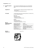
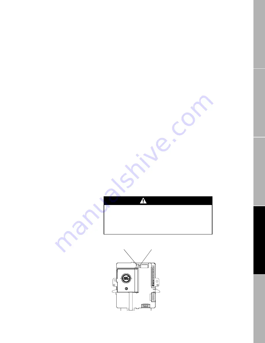
initialization, the RFT9709 diagnostic LED (see Figure 3-1) remains on
continuously, while the RFT9709 performs a self-diagnostic test. After
initialization is completed, the LED blinks ON once per second to
indicate proper RFT9709 operation.
At startup, the power source must provide a minimum of 2 amperes of
inrush current at a minimum of 11 volts and a maximum of 7 watts at the
RFT9709 power input terminals.
3.2
Flowmeter zeroing
Flowmeter zeroing establishes flowmeter response to zero flow and sets
a baseline for flow measurement.
• Zeroing is necessary when the flowmeter is first put into operation, and
if either the transmitter or sensor is replaced or reinstalled.
• Zeroing is not necessary every time power is applied to the transmitter,
or when a new process fluid is run through the sensor.
• Zeroing is accomplished with the RFT9709 zero button (see
Figure 3-1) or a special version of the ProLink program. The HART
Communicator cannot be used for zeroing the flowmeter. (Contact the
factory for additional ProLink information.)
• The zeroing procedure is described on page 28.
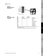
Figure 3-1.
Diagnostic LED and zero
button
CAUTION
Failure to zero the flowmeter at initial startup could
cause the transmitter to produce inaccurate signals.
Zero the flowmeter before putting the flowmeter in
operation.
Zero button
Diagnostic LED
09start.fm Page 27 Tuesday, March 2, 1999 9:16 AM
Summary of Contents for Fisher-Rosemount RFT9709
Page 1: ...Model RFT9709 Transmitter Instruction Manual March 1999 ...
Page 2: ......
Page 4: ......
Page 8: ...iv RFT9709 Transmitter Instruction Manual ...
Page 34: ...26 RFT9709 Transmitter Instruction Manual ...
Page 52: ...44 RFT9709 Transmitter Instruction Manual ...
Page 60: ...52 RFT9709 Transmitter Instruction Manual ...
Page 62: ...54 RFT9709 Transmitter Instruction Manual ...
Page 72: ...64 RFT9709 Transmitter Instruction Manual ...
Page 73: ......

