36
RFT9709 Transmitter Instruction Manual
Troubleshooting
continued
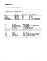
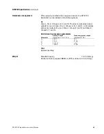
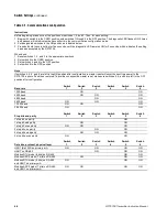
Table 4-2. Normal resistance for flowmeter circuits
Table 4-3. Input and output ratings
Notes
• Temperature sensor value increases 0.38675 ohms per °C increase in temperature.
• Nominal resistance values will vary 40% per 100°C. However, confirming an open coil or shorted coil is more important than
any slight deviation from the resistance values presented below.
• Resistance across terminals 6 and 8 (right pickoff) should be within 10% of resistance across terminals 5 and 9 (left pickoff).
• Resistance values depend on the sensor model and date of manufacture.
Circuit
Wire colors
Sensor terminals
Nominal resistance range
Drive Coil
Brown to Red
1 to 2
8 to 2650
Ω
Left Pickoff
Green to White
5 to 9
15.9 to 300
Ω
Right Pickoff
Blue to Gray
6 to 8
15.9 to 300
Ω
Temperature Sensor
Orange to Violet
3 to 7
35 to 175
Ω
depending on process fluid
Lead Length Compensator
Yellow to Violet
4 to 7
35 to 175
Ω
depending on process fluid
Transmitter terminal
number
Input or output
Approximate value
1 to 2
Drive signal output to sensor
1.2 to 14 V peak-to-peak at flow tube natural frequency
3 to 4
Lead length compensator input
10 mVDC maximum
5 to 9
Left pickoff input
3.4 mV/Hz peak-to-peak sine wave
6 to 8
Right pickoff input
3.4 mV/Hz peak-to-peak sine wave
7 to 4
Temperature input
30 mV at 0°C, +0.14 mVDC per °C
Power terminals (+ to –)
Line voltage input
11 to 30 VDC
11 to 12
Primary mA output
4-20 mA
13 to 14
Secondary mA output
4-20 mA
15 to 16
RS-485 I/O
±5 V square wave
17 to 18*
*Optional configuration
Frequency/pulse output
23 VDC peak-to-peak square wave (+23 VDC at zero flow)
19 to 18*
Zero in progress
23 VDC when not in progress, 0 VDC when in progress
19 to 18*
Flow direction output
23 VDC with forward, 0 VDC with reverse
19 to 18*
Alarm output
23 VDC normal, 0 VDC with fault
20 to 18*
Remote zero input
23 VDC
21 to 22*
Pressure transmitter input
0.3 to 11 VDC
09shoot.fm Page 36 Tuesday, March 2, 1999 9:26 AM
Summary of Contents for Fisher-Rosemount RFT9709
Page 1: ...Model RFT9709 Transmitter Instruction Manual March 1999 ...
Page 2: ......
Page 4: ......
Page 8: ...iv RFT9709 Transmitter Instruction Manual ...
Page 34: ...26 RFT9709 Transmitter Instruction Manual ...
Page 52: ...44 RFT9709 Transmitter Instruction Manual ...
Page 60: ...52 RFT9709 Transmitter Instruction Manual ...
Page 62: ...54 RFT9709 Transmitter Instruction Manual ...
Page 72: ...64 RFT9709 Transmitter Instruction Manual ...
Page 73: ......


