RFT9709 Transmitter Instruction Manual
47
Appendix
C
Switch Settings
C.1
Configuration switches
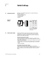
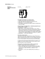
Switches on the RFT9709 (see Figure C-1) control the following
transmitter functions:
• Communications settings
• mA output settings
• Zeroing method
• Security
Figure C-1.
Switches
C.2
Communication settings
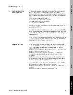
Switch 5 enables the user to choose the standard communication
configuration, or user-defined parameters. With switch 8 in the ON
(CNFG) position, switches 1 through 6 can be used for setting user-
defined communication parameters.
Standard communication setting
To use the standard communication configuration, set switch 5 to the
STD position. Setting the switch in this position establishes the following
communication parameters:
• HART protocol, at 1200 baud, on the primary-variable (PV) mA output
• Modbus protocol, in RTU mode (8 bit), at 9600 baud, on the RS-485
output
• 1 stop bit, odd parity
User-defined communication settings
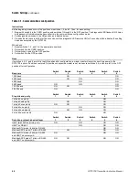
To establish user-defined settings, set switches as instructed in
Table C-1, page 48. In the user-defined setting, until they are changed or
after a master reset, communication parameters match those listed
above.
1 2 3 4 5 6 7 8
Switches at left shown in
OFF position.
Switch
number
Switch position
OFF
ON
1
OFF
SEC1
2
OFF
SEC2
3
OFF
SEC3
4
5
STD
USR
6
7
DOWN
UP
8
OP
CONFIG
09switch.fm Page 47 Tuesday, March 2, 1999 9:36 AM
Summary of Contents for Fisher-Rosemount RFT9709
Page 1: ...Model RFT9709 Transmitter Instruction Manual March 1999 ...
Page 2: ......
Page 4: ......
Page 8: ...iv RFT9709 Transmitter Instruction Manual ...
Page 34: ...26 RFT9709 Transmitter Instruction Manual ...
Page 52: ...44 RFT9709 Transmitter Instruction Manual ...
Page 60: ...52 RFT9709 Transmitter Instruction Manual ...
Page 62: ...54 RFT9709 Transmitter Instruction Manual ...
Page 72: ...64 RFT9709 Transmitter Instruction Manual ...
Page 73: ......

