50
RFT9709 Transmitter Instruction Manual
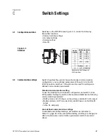
Switch Settings
continued
Security mode 8
When security is set for mode 8, the RFT9709 meets security
requirements for custody transfer described in National Institute of
Standards and Technology (NIST) Handbook 44.
Once the RFT9709 is configured for security mode 8, the security mode
cannot be changed unless a master reset is performed. A master reset
causes all configuration parameters to return to their default values, and
requires complete characterization and reconfiguration of the
transmitter. See Section 4.6, page 37.
If the user attempts to enter a new security mode or change the
RFT9709 configuration after entering security mode 8:
• Internal totalizers stop counting
• The frequency/pulse output goes to 0 Hz
• mA outputs go to 4 mA
• Event registers record changes made to defined configuration and
calibration parameters. See Section 3.3, page 29.
The security breach continues, and totalizers and outputs remain
inactive, until the RFT9709 is reconfigured for security mode 8, or until a
master reset has been performed. Custody transfer event registers are
not affected by a master reset.
Before entering security mode 8, perform milliamp trim and/or test
procedures, if necessary. Milliamp output trim, milliamp output test, and
frequency/pulse output test cannot be performed after security mode 8
is entered. A special version of the ProLink program is required to
perform these procedures. A HART Communicator cannot be used.
(Contact the factory for additional ProLink information.) See
Output test
and trim
, page 33.
To enter security mode 8:
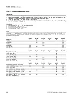
1. Note the position of switch 5.
2. Set switch 8 to the ON position. The diagnostic LED flashes ON three
times and pauses, which indicates the RFT9709 is in the
configuration mode.
3. Set switches 1, 2, and 3 to the ON position.
4. Set switches 4, 5, and 6 to the OFF position.
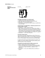
5. Press and hold the zero button for 5 seconds. The diagnostic LED will
remain on for 2 to 3 seconds to indicate security mode 8 has been
entered. Figure C-2 illustrates the location of the zero button and
diagnostic LED.
6. Reset switch 5 to the desired position (as noted in Step 1).
7. Reset switch 8 to the OFF (OPERATE) position. The diagnostic LED
flashes on once per second (25% on, 75% off), which indicates the
RFT9709 is in the normal operating mode.
09switch.fm Page 50 Tuesday, March 2, 1999 9:36 AM
Summary of Contents for Fisher-Rosemount RFT9709
Page 1: ...Model RFT9709 Transmitter Instruction Manual March 1999 ...
Page 2: ......
Page 4: ......
Page 8: ...iv RFT9709 Transmitter Instruction Manual ...
Page 34: ...26 RFT9709 Transmitter Instruction Manual ...
Page 52: ...44 RFT9709 Transmitter Instruction Manual ...
Page 60: ...52 RFT9709 Transmitter Instruction Manual ...
Page 62: ...54 RFT9709 Transmitter Instruction Manual ...
Page 72: ...64 RFT9709 Transmitter Instruction Manual ...
Page 73: ......

