RFT9709 Transmitter Instruction Manual
53
Appendix
D
Open Collector Configuration
If desired, the RFT9709 frequency/pulse and control outputs can be
configured for open collector mode.
• When used in the open collector mode, the output circuit is rated to
30 VDC, with 0.1 ampere maximum sinking capability.
• To wire the RFT9709 outputs, see
Installation
Step 2
, starting on
page 7.
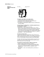
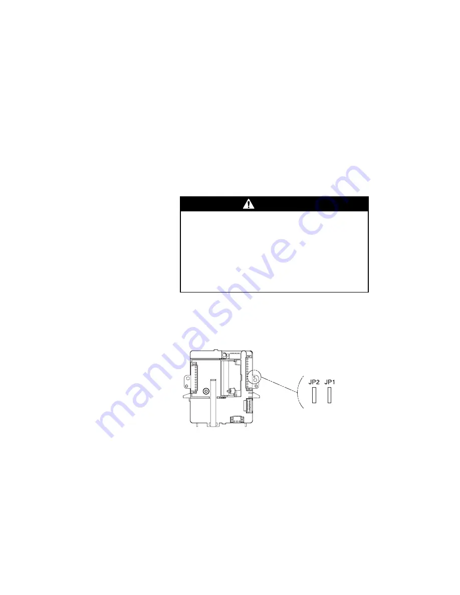
To configure outputs for open collector mode, jumpers on the RFT9709
must be cut. Refer to Figure D-1.
Figure D-1.
Configuring open collector
mode
CAUTION
The open collector configuration procedure
cannot be reversed.
Configuring the frequency/pulse or control outputs for
open collector mode requires jumpers on the RFT9709
to be cut. Once cut, the jumpers cannot be reconnected.
Do not cut jumpers unless you are certain your process
requires outputs in open collector mode.
• To configure the frequency/pulse output for
open collector mode, cut jumper JP2.
• To configure the control output for open
collector mode, cut jumper JP1.
09openc.fm Page 53 Tuesday, March 2, 1999 9:41 AM
Summary of Contents for Fisher-Rosemount RFT9709
Page 1: ...Model RFT9709 Transmitter Instruction Manual March 1999 ...
Page 2: ......
Page 4: ......
Page 8: ...iv RFT9709 Transmitter Instruction Manual ...
Page 34: ...26 RFT9709 Transmitter Instruction Manual ...
Page 52: ...44 RFT9709 Transmitter Instruction Manual ...
Page 60: ...52 RFT9709 Transmitter Instruction Manual ...
Page 62: ...54 RFT9709 Transmitter Instruction Manual ...
Page 72: ...64 RFT9709 Transmitter Instruction Manual ...
Page 73: ......

