60
RFT9709 Transmitter Instruction Manual
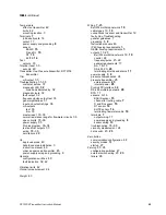
Index
continued
Downscale
configuration switches
49
fault indication
32, 42
DP cell. See Pressure transmitter
DT sensor. See Sensor; Wiring
E
Effect. See Environmental effects
ELITE sensor. See Sensor; Wiring
Environmental effects on sensor and transmitter
42
Environmental limits
42
Event registers
29
parameters that affect
29
security mode 8
50–51
External zero
external switch wiring
23, 23
F
F sensor. See Sensor; Wiring
Fault output. See also Troubleshooting
configuration switches
49
specification
42
troubleshooting with
32
Flowmeter
cable
10, 10
connections to sensor and RFT9709
12
instruction manual for cable preparation
46
maximum length to sensor
3
sensor wiring
BASIS, D, and DL
15
DT
16
ELITE
14
terminating
10
normal resistance range for flowmeter circuits
36
proving
2
Frequency/pulse output
21–22
. See also Outputs
open collector configuration
53, 53
open collector mode
21–22
security mode 8
50
specification
40
test
33, 42
totalizer reset
30
Functional specifications
40–42
Fuse
42
G
Grounding
ground nut
8
intrinsically safe installations
8
power supply and
8
H
Handbook 44
event registers
29
security mode 8
50
HART Communicator. See HART protocol; ProLink
program
HART protocol. See also ProLink program
Bell 202 multidrop network
19
communication configuration
48
configuration and calibration
1
configuration switches
47
mA outputs
18
master reset
37
master reset default values
38
pressure transmitter input specification
41
RS-485 output
20
specifications
communication output
41
pressure transmitter
41
Hazardous areas. See also Intrinsically safe installations
agency approvals
43
installing in
3
order an approved transmitter
45
Humidity limits
42
I
Initialization
27
. See also Startup
27
Instruction manuals
list of
46
proving
2
Intrinsically safe installations
3
agency approvals
43
external zero switch wiring
23
grounding
8
order an approved transmitter
45
output wiring
17
power-supply wiring
8
pressure transmitter wiring
25
sensor wiring
9, 12
IP65 housing
conduit openings
5
dimensions
6
factory supplied
5
installation
5
mounting options
4
user supplied
5
wiring guidelines
7
L
LED. See Diagnostic LED
Location
3
Low-flow cutoff specification
42
M
mA outputs
18–19
. See also Outputs
Bell 202 multidrop network
19
communication configuration
47–48
configuration switches
47–48
master reset default value
38
performance and requirements
18
pressure transmitter input specification
41
rangeability specification
40
security mode 8
50
specification
40
temperature effect on
42
test
33, 42
trim
33
09__a.IX Page 60 Tuesday, March 2, 1999 9:52 AM
Summary of Contents for Fisher-Rosemount RFT9709
Page 1: ...Model RFT9709 Transmitter Instruction Manual March 1999 ...
Page 2: ......
Page 4: ......
Page 8: ...iv RFT9709 Transmitter Instruction Manual ...
Page 34: ...26 RFT9709 Transmitter Instruction Manual ...
Page 52: ...44 RFT9709 Transmitter Instruction Manual ...
Page 60: ...52 RFT9709 Transmitter Instruction Manual ...
Page 62: ...54 RFT9709 Transmitter Instruction Manual ...
Page 72: ...64 RFT9709 Transmitter Instruction Manual ...
Page 73: ......

