RFT9709 Transmitter Instruction Manual
iii
Table of Contents
continued
Tables
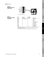
Table 2-1
Sensor-wiring terminal designations. . . . . . . . . 13
Table 2-2
Output-wiring terminal designations . . . . . . . . . 17
Table 2-3
Sensors affected by pressure . . . . . . . . . . . . . . 24
Table 3-1
Parameters that affect event registers . . . . . . . 29
Table 4-1
Conditions indicated by diagnostic LED . . . . . . 32
Table 4-2
Normal resistance for flowmeter circuits. . . . . . 36
Table 4-3
Input and output ratings . . . . . . . . . . . . . . . . . . 36
Table 4-4
Default values after a master reset. . . . . . . . . . 38
Table A
Performance specifications. . . . . . . . . . . . . . . . 39
Table B
RFT9709 model number matrix . . . . . . . . . . . . 45
Table C-1
Communications configuration . . . . . . . . . . . . . 48
Table C-2
Security modes . . . . . . . . . . . . . . . . . . . . . . . . . 49
Figures
RFT9709 components . . . . . . . . . . . . . . . . . . .
2
Figure 1-1
RFT9709 approvals tag . . . . . . . . . . . . . . . . . .
3
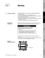
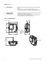
Figure 1-2
RFT9709 dimensions . . . . . . . . . . . . . . . . . . . .
4
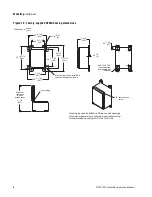
Figure 1-3
Factory-supplied NEMA-housing dimensions. .
6
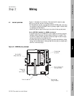
Figure 2-1
RFT9709 wiring terminals. . . . . . . . . . . . . . . . .
7
Figure 2-2
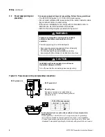
Power-supply wiring and grounding
connections . . . . . . . . . . . . . . . . . . . . . . . .
8
Figure 2-3
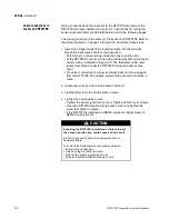
Cable types. . . . . . . . . . . . . . . . . . . . . . . . . . . . 10
Figure 2-4
Terminating flowmeter cable. . . . . . . . . . . . . . . 10
Figure 2-5
RFT9709 terminals for sensor wiring . . . . . . . . 13
Figure 2-6
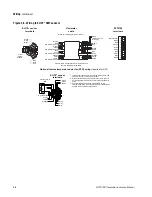
Wiring to ELITE
®
CMF sensors . . . . . . . . . . . . 14
Figure 2-7
Wiring to BASIS
®
F, Model D, and
DL sensors . . . . . . . . . . . . . . . . . . . . . . . . . 15
Figure 2-8
Wiring to Model DT sensors . . . . . . . . . . . . . . . 16
Figure 2-9
Terminating output-wiring shields and drains . . 17
Figure 2-10
mA output terminals . . . . . . . . . . . . . . . . . . . . . 18
Figure 2-11
Typical HART
®
network wiring . . . . . . . . . . . . . 19
Figure 2-12
RS-485 wiring . . . . . . . . . . . . . . . . . . . . . . . . . . 20
Figure 2-13
Frequency/pulse output terminals. . . . . . . . . . . 21
Figure 2-14
Control output terminals . . . . . . . . . . . . . . . . . . 22
Figure 2-15
Remote-zero switch wiring . . . . . . . . . . . . . . . . 23
Figure 2-16a
Pressure transmitter wiring, internally
powered . . . . . . . . . . . . . . . . . . . . . . . . . . . 25
Figure 2-16b
Pressure transmitter wiring, externally powered
(multidrop network) . . . . . . . . . . . . . . . . . . 25
Figure 3-1
Diagnostic LED and zero button . . . . . . . . . . . . 27
Figure 4-1
Diagnostic LED . . . . . . . . . . . . . . . . . . . . . . . . . 32
Figure 4-2
ProLink
®
PC-Interface connections . . . . . . . . . 34
Figure 4-3
Power-supply wiring and grounding terminals . 35
Figure C-1
Switches . . . . . . . . . . . . . . . . . . . . . . . . . . . . . . 47
Figure C-2
Diagnostic LED and zero button . . . . . . . . . . . . 51
Figure D-1
Configuring open collector mode . . . . . . . . . . . 53
09__a.TOC Page iii Monday, March 1, 1999 4:20 PM
Summary of Contents for Fisher-Rosemount RFT9709
Page 1: ...Model RFT9709 Transmitter Instruction Manual March 1999 ...
Page 2: ......
Page 4: ......
Page 8: ...iv RFT9709 Transmitter Instruction Manual ...
Page 34: ...26 RFT9709 Transmitter Instruction Manual ...
Page 52: ...44 RFT9709 Transmitter Instruction Manual ...
Page 60: ...52 RFT9709 Transmitter Instruction Manual ...
Page 62: ...54 RFT9709 Transmitter Instruction Manual ...
Page 72: ...64 RFT9709 Transmitter Instruction Manual ...
Page 73: ......


