54
RFT9739 Rack-Mount Transmitter Instruction Manual
Output Wiring
continued
5.8
Remote-zero switch
The transmitter can be zeroed from a remote switch. If the transmitter
display indicates flow rate, this contact will zero the flowmeter. If the
transmitter display indicates flow total, this contact will reset the flow
total.
• Section 6.4, page 65, describes the flowmeter zeroing procedure.
• Section 6.5, page 67, describes the totalizer reset procedure.
The switch must be a momentary-type contact, normally open, close to
zero, and must carry 1 mA of current in the closed position. The open
circuit voltage is 5 VDC.
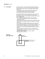
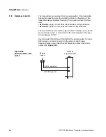
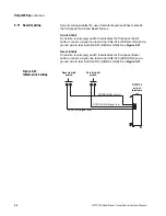
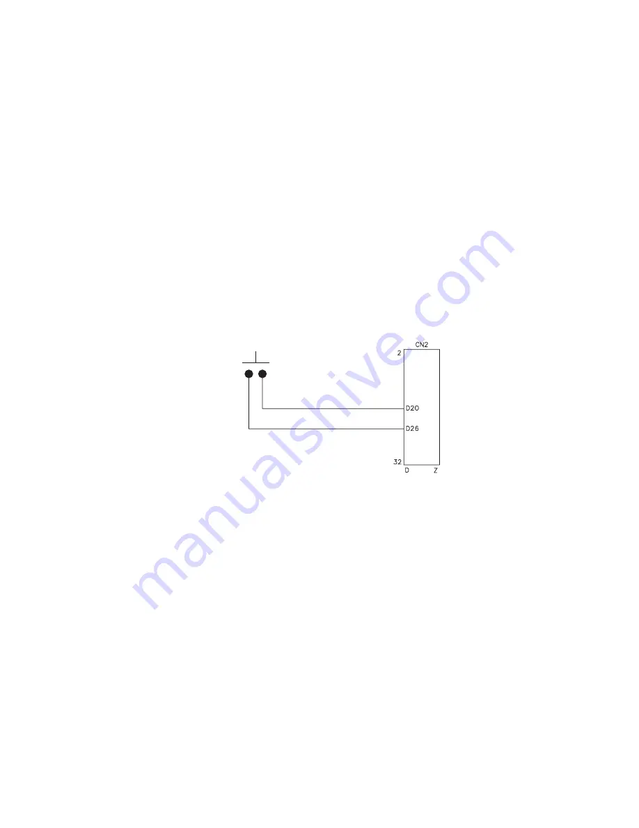
Use terminals CN2-D20 and CN2-D26 for the remote switch. Terminal
D26 serves as a common return for the external-switch input,
frequency/pulse output, dual-channel frequency output, and control
output. See Figure 5-28.
Figure 5-28.
Wiring to remote-zero
switch
Remote
switch
RFT9739
output terminals
ZERO+ (signal line)
RETURN (ground)
Summary of Contents for Fisher Rosemount RFT9739
Page 1: ...Model RFT9739 Rack Mount Transmitter Instruction Manual Version 3 Transmitters February 2000 ...
Page 2: ......
Page 4: ......
Page 20: ...10 RFT9739 Rack Mount Transmitter Instruction Manual ...
Page 26: ...16 RFT9739 Rack Mount Transmitter Instruction Manual ...
Page 92: ...82 RFT9739 Rack Mount Transmitter Instruction Manual ...
Page 100: ...90 RFT9739 Rack Mount Transmitter Instruction Manual ...
Page 110: ...100 RFT9739 Rack Mount Transmitter Instruction Manual ...
Page 112: ...102 RFT9739 Rack Mount Transmitter Instruction Manual ...
Page 120: ...110 RFT9739 Rack Mount Transmitter Instruction Manual ...
Page 122: ...112 RFT9739 Rack Mount Transmitter Instruction Manual ...
Page 129: ......

