56
RFT9739 Rack-Mount Transmitter Instruction Manual
Output Wiring
continued
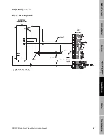
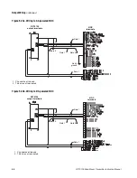
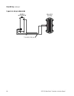
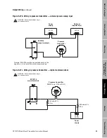
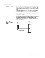
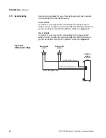
Figure 5-29. RS-485 wiring
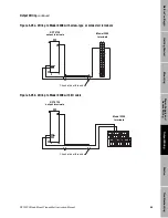
5.10 Bell 202 multidrop
network
The RFT9739 can be configured to communicate for any one of the
following options:
• HART protocol over the RS-485 standard
• HART protocol over the Bell 202 standard
• Modbus protocol over the RS-485 standard
• Modbus protocol over the RS-485 standard and HART protocol over
the Bell 202 standard
For communications configuration instructions, see "Communication
configuration mode," page 61. For RS-485 network wiring, see
Section 5.9, page 55.
Devices in a Bell 202 multidrop network communicate by sending and
receiving signals to and from one another. HART protocol supports up to
15 transmitters in a Bell 202 multidrop network. The actual maximum
number depends upon the type of transmitters, the method of
installation, and other external factors. Other Rosemount SMART
FAMILY transmitters can also participate in a HART-compatible network.
• A Bell 202 multidrop network uses twisted-pair wire, and allows only
digital communication. Digital communication requires a sample rate of
2 to 31 seconds at 1200 baud.
• A HART Communicator or other HART-compatible control system can
communicate with any device in the network over the same 2-wire pair.
Using multiple transmitters in a HART-compatible network requires
assigning a unique address from 1 to 15 to each transmitter.
• Assigning an address of 1 to 15 to the transmitter causes the primary
mA output to remain at a constant 4 mA level.
• The primary mA output must produce a 4-20 mA current for the Bell
202 physical layer. The Bell 202 layer will not work with the primary mA
output configured as a 0-20 mA output when the current output is
0 mA.
RFT9739
Z22
D22
RFT9739
Z22
D22
A
B
A
B
RFT9739
Z22
D22
RFT9739
Z22
D22
One RFT9739 and
a host controller
Multiple RFT9739s and
a host controller
Host
controller
Host
controller
See note
See note
See note
See note
For long-distance communication, or if noise from an external source interferes with the
signal, install 120-ohm ½-watt resistors across terminals of both end devices.
Summary of Contents for Fisher Rosemount RFT9739
Page 1: ...Model RFT9739 Rack Mount Transmitter Instruction Manual Version 3 Transmitters February 2000 ...
Page 2: ......
Page 4: ......
Page 20: ...10 RFT9739 Rack Mount Transmitter Instruction Manual ...
Page 26: ...16 RFT9739 Rack Mount Transmitter Instruction Manual ...
Page 92: ...82 RFT9739 Rack Mount Transmitter Instruction Manual ...
Page 100: ...90 RFT9739 Rack Mount Transmitter Instruction Manual ...
Page 110: ...100 RFT9739 Rack Mount Transmitter Instruction Manual ...
Page 112: ...102 RFT9739 Rack Mount Transmitter Instruction Manual ...
Page 120: ...110 RFT9739 Rack Mount Transmitter Instruction Manual ...
Page 122: ...112 RFT9739 Rack Mount Transmitter Instruction Manual ...
Page 129: ......


