74
RFT9739 Rack-Mount Transmitter Instruction Manual
Troubleshooting
continued
Overrange and sensor
error messages
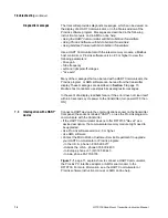
If a sensor failure occurs, if the sensor cable is faulty, or if measured flow,
measured temperature, or measured density go outside the sensor
limits, the display produces one of the following messages:
• "Sensor Error"
• "Drive Overrng"
• "Input Overrange"
• "Temp Overrange"
• "Dens Overrng"
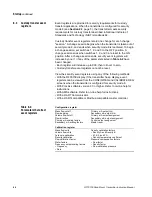
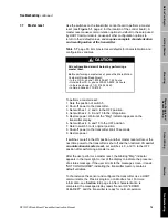
To interpret overrange and sensor error messages, use the transmitter
fault output levels, a digital multimeter (DMM) or other reference device,
and refer to Table 7-3, page 75, for corrective actions.
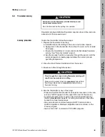
• Turn off power to the transmitter before unplugging terminal blocks.
• Unplug terminal blocks from the transmitter back panel to check
circuits.
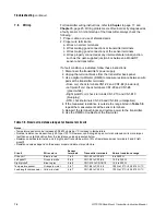
Slug flow
Programmed slug flow limits enable transmitter outputs and the display
to indicate conditions such as slug flow (gas slugs in a liquid flow
stream). Such conditions adversely affect sensor performance by
causing erratic vibration of the flow tubes, which in turn causes the
transmitter to produce inaccurate flow signals.
If the user programs slug limits, a slug flow condition causes the
following to occur:
1. The message display reads "SLUG FLOW".
2. The frequency/pulse output goes to 0 Hz.
3. The mA outputs indicating the flow rate go to the level that represents
zero flow.
The flowmeter resumes normal operation when liquid fills the flow tubes
and density stabilizes within the programmed slug flow limits.
The user can also program a slug duration, from 0 to 60 seconds, into
the configuration of an RFT9739. If process density goes outside a slug
flow limit, flow outputs hold their last measured value for the period of
time established as the slug duration.
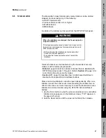
Table 7-4, page 75 summarizes possible slug flow errors and lists
typical corrective actions.
Output saturated
messages
If an output variable exceeds its upper range limit, the display message
reads "Freq Overrange", "mA 1 Saturated" or "mA 2 Saturated". The
message can mean the output variable has exceeded appropriate limits
for the process, or can mean the user needs to change measurement
units.
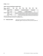
Table 7-4, page 75 summarizes possible output saturated messages
and lists typical corrective actions.
Summary of Contents for Fisher Rosemount RFT9739
Page 1: ...Model RFT9739 Rack Mount Transmitter Instruction Manual Version 3 Transmitters February 2000 ...
Page 2: ......
Page 4: ......
Page 20: ...10 RFT9739 Rack Mount Transmitter Instruction Manual ...
Page 26: ...16 RFT9739 Rack Mount Transmitter Instruction Manual ...
Page 92: ...82 RFT9739 Rack Mount Transmitter Instruction Manual ...
Page 100: ...90 RFT9739 Rack Mount Transmitter Instruction Manual ...
Page 110: ...100 RFT9739 Rack Mount Transmitter Instruction Manual ...
Page 112: ...102 RFT9739 Rack Mount Transmitter Instruction Manual ...
Page 120: ...110 RFT9739 Rack Mount Transmitter Instruction Manual ...
Page 122: ...112 RFT9739 Rack Mount Transmitter Instruction Manual ...
Page 129: ......

