78
RFT9739 Rack-Mount Transmitter Instruction Manual
Troubleshooting
continued
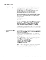
7.6
Wiring
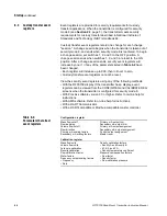
For transmitter wiring instructions, refer to Chapter 4, page 17, and
Chapter 5, page 25. Wiring problems are often incorrectly diagnosed as
a faulty sensor. At initial startup of the transmitter, always check the
following:
1. Proper cable, and use of shielded pairs
2. Proper wire termination
a. Wires on correct terminals
b. Wires making good connections at transmitter terminals
c. Wires making good connections at the sensor terminals
d. Wires properly connected at any intermediate terminal junction,
such as the user-supplied junction box between a Model DT
sensor and transmitter.
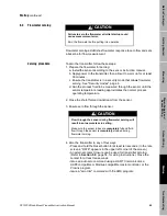
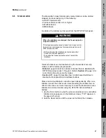
If a fault condition is indicated, follow these instructions:
1. Disconnect the transmitter's power supply.
2. Unplug the terminal blocks from the transmitter back panel.
3. Use a digital multimeter (DMM) to measure resistance between wire
pairs at the transmitter terminals:
- Drive coil, check terminals CN1-Z2 and CN1-B2 (brown/red)
- Left pickoff coil, check terminals CN1-Z8 and CN1-B8
(green/white)
- Right pickoff coil, check terminals CN1-Z10 and CN1-B10
(blue/gray)
- RTD, check terminals CN1-Z6 and CN1-B4 (violet/yellow)
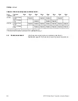
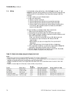
4. If the measured resistance is outside the range listed in Table 7-6,
repeat the measurements at the sensor terminals.
5. Reinsert the terminal blocks and restore power to the transmitter.
6. Use the DMM to troubleshoot the flowmeter.
Table 7-6. Nominal resistance ranges for flowmeter circuits
Notes
• Temperature sensor value increases 0.38675 ohms per
°
C increase in temperature
• Nominal resistance values will vary 40% per 100
°
C. However, confirming an open coil or shortened coil is more impor-
tant than any slight deviation from the resistance values presented below.
• Resistance across terminals 6 and 8 (right pickoff) should be within 10% of resistance across terminals 5 and 9 (left
pickoff).
• Resistance values depend on the sensor model and date of manufacture.
Circuit
Wire colors
Sensor
terminals
Transmitter terminals
Normal resistance range
Drive coil
Brown to red
1 to 2
CN1-Z2 to CN1-B2
8 to 2650
Ω
Left pickoff
Green to white
5 to 9
CN1-Z8 to CN1-B8
15.9 to 300
Ω
Right pickoff
Blue to gray
6 to 8
CN1-Z10 to CN1-B10
15.9 to 300
Ω
Temperature sensor
Orange to violet
3 to 7
CN1-B6 to CN1-Z6
100
Ω
at 0
°
C + 0.38675
Ω
/
°
C
Lead length compensator
Yellow to violet
4 to 7
CN1-B4 to CN1-Z6
100
Ω
at 0
°
C + 0.38675
Ω
/
°
C
Summary of Contents for Fisher Rosemount RFT9739
Page 1: ...Model RFT9739 Rack Mount Transmitter Instruction Manual Version 3 Transmitters February 2000 ...
Page 2: ......
Page 4: ......
Page 20: ...10 RFT9739 Rack Mount Transmitter Instruction Manual ...
Page 26: ...16 RFT9739 Rack Mount Transmitter Instruction Manual ...
Page 92: ...82 RFT9739 Rack Mount Transmitter Instruction Manual ...
Page 100: ...90 RFT9739 Rack Mount Transmitter Instruction Manual ...
Page 110: ...100 RFT9739 Rack Mount Transmitter Instruction Manual ...
Page 112: ...102 RFT9739 Rack Mount Transmitter Instruction Manual ...
Page 120: ...110 RFT9739 Rack Mount Transmitter Instruction Manual ...
Page 122: ...112 RFT9739 Rack Mount Transmitter Instruction Manual ...
Page 129: ......

