18
RFT9739 Rack-Mount Transmitter Instruction Manual
Power-Supply and Sensor Wiring
continued
Power-supply wiring
Some European applications require installation of AC power-supply
wiring to connector CN2, terminals D2 (AC+), D6 (AC–), and Z2 (GND).
In Europe, before making AC power-supply wiring connections at
CN2,
contact the Micro Motion Customer Service Department. In
Europe, phone +31 (0) 318 549 443.
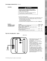
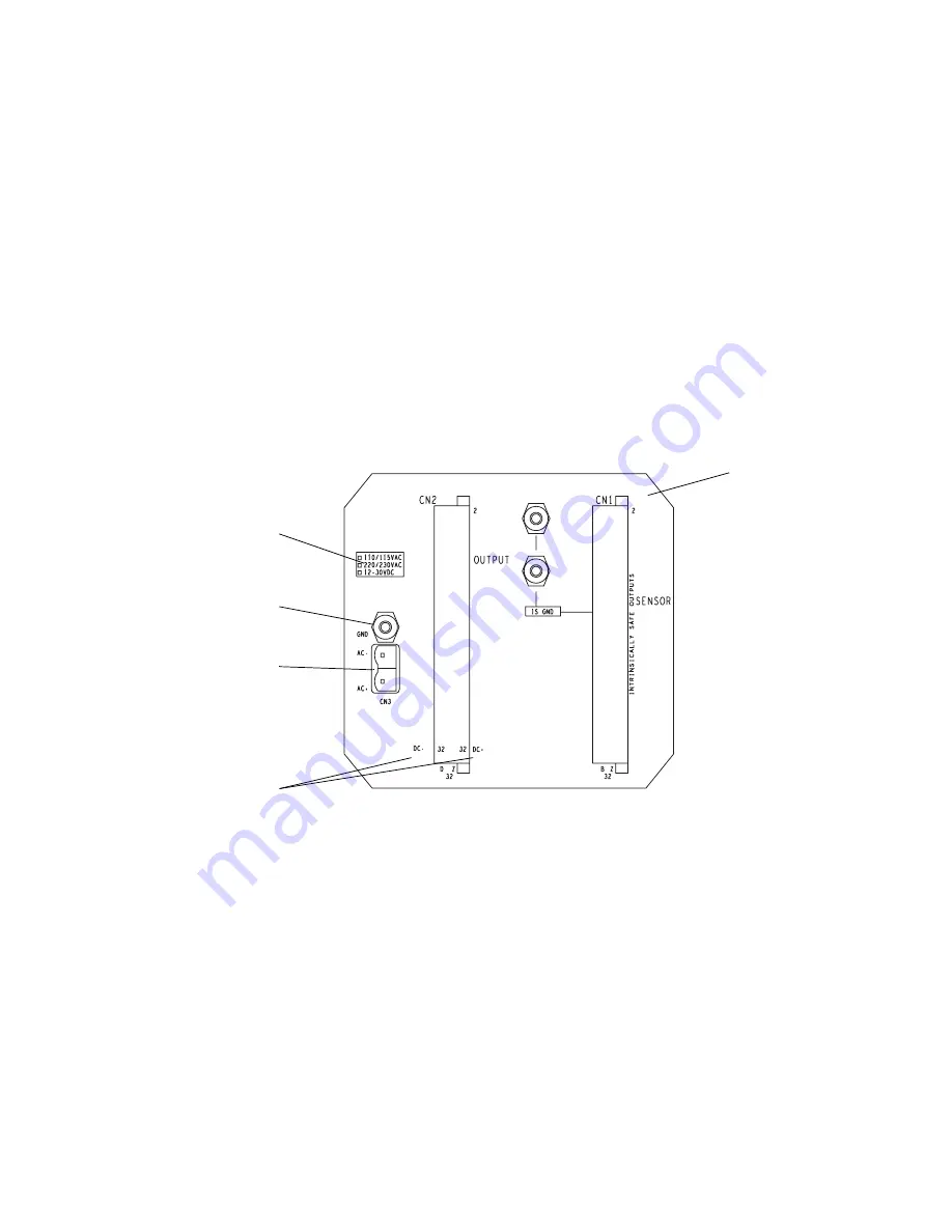
To install power-supply wiring, refer to Figure 4-1 and follow these
steps:
1. Match power-supply voltage to voltage indicated on the label in the
upper corner of the transmitter back panel.
2. Connect AC power-supply wiring at connector CN3 and the ground
lug directly above connector CN3; or connect DC power-supply wiring
at connector CN2, to terminals Z32 (DC+) and D32 (DC–).
3. Ground the transmitter as instructed below.
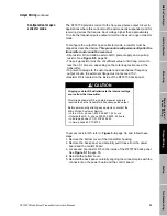
Figure 4-1. Power-supply wiring terminals
Power-supply
voltage label
AC power
ground
AC power -supply
terminals
DC power-supply
terminals
RFT9739
back panel
Summary of Contents for Fisher Rosemount RFT9739
Page 1: ...Model RFT9739 Rack Mount Transmitter Instruction Manual Version 3 Transmitters February 2000 ...
Page 2: ......
Page 4: ......
Page 20: ...10 RFT9739 Rack Mount Transmitter Instruction Manual ...
Page 26: ...16 RFT9739 Rack Mount Transmitter Instruction Manual ...
Page 92: ...82 RFT9739 Rack Mount Transmitter Instruction Manual ...
Page 100: ...90 RFT9739 Rack Mount Transmitter Instruction Manual ...
Page 110: ...100 RFT9739 Rack Mount Transmitter Instruction Manual ...
Page 112: ...102 RFT9739 Rack Mount Transmitter Instruction Manual ...
Page 120: ...110 RFT9739 Rack Mount Transmitter Instruction Manual ...
Page 122: ...112 RFT9739 Rack Mount Transmitter Instruction Manual ...
Page 129: ......


