20
RFT9739 Rack-Mount Transmitter Instruction Manual
Power-Supply and Sensor Wiring
continued
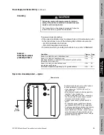
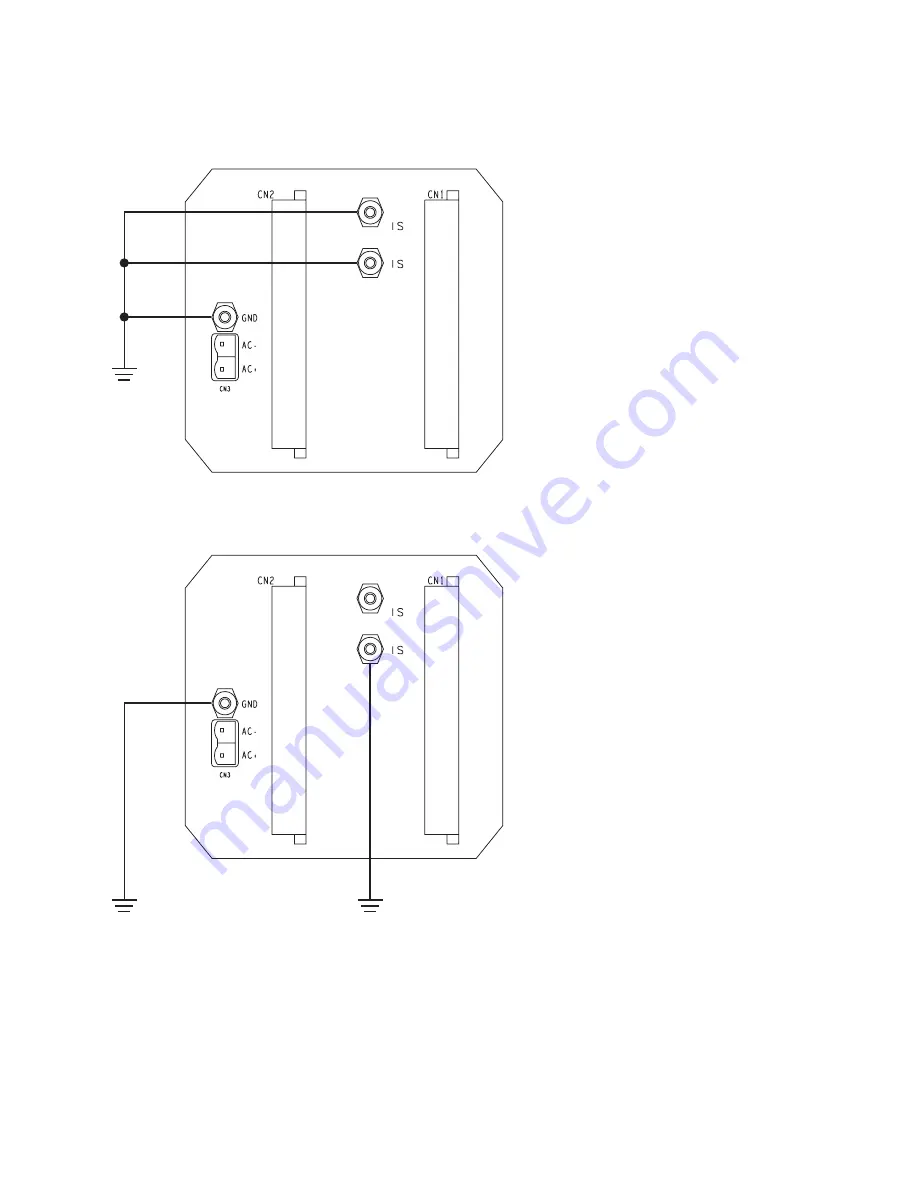
Figure 4-2b. Grounding detail — hazardous-area sensor installations
Figure 4-2c. Grounding detail — high-integrity I.S. installations
Earth
ground
If national standards are not in effect, adhere
to these guidelines for grounding:
• Use copper wire, 14 AWG (2.5 mm²) or
larger wire size.
• Keep all ground leads as short as possible,
less than 1 ohm impedance.
• Connect I.S. grounds and power-supply
ground directly to earth.
High integrity
I.S. ground
Earth
ground
If national standards are not in effect, adhere
to these guidelines for grounding:
• Use copper wire, 14 AWG (2.5 mm²) or
larger wire size.
• Keep all ground leads as short as possible,
less than 1 ohm impedance.
• A factory-installed ground wire, connecting
the I.S. ground and power-supply ground
terminals, must be removed.
• Connect ground lead from power-supply
ground terminal directly to earth ground.
• To achieve potential equalization, connect
the I.S. ground terminal to the appropriate
ground terminals within the hazardous area,
using a potential equalizing line.
• I.S. ground wire must not be routed with
other wires.
Summary of Contents for Fisher Rosemount RFT9739
Page 1: ...Model RFT9739 Rack Mount Transmitter Instruction Manual Version 3 Transmitters February 2000 ...
Page 2: ......
Page 4: ......
Page 20: ...10 RFT9739 Rack Mount Transmitter Instruction Manual ...
Page 26: ...16 RFT9739 Rack Mount Transmitter Instruction Manual ...
Page 92: ...82 RFT9739 Rack Mount Transmitter Instruction Manual ...
Page 100: ...90 RFT9739 Rack Mount Transmitter Instruction Manual ...
Page 110: ...100 RFT9739 Rack Mount Transmitter Instruction Manual ...
Page 112: ...102 RFT9739 Rack Mount Transmitter Instruction Manual ...
Page 120: ...110 RFT9739 Rack Mount Transmitter Instruction Manual ...
Page 122: ...112 RFT9739 Rack Mount Transmitter Instruction Manual ...
Page 129: ......


