RFT9739 Rack-Mount Transmitter Instruction Manual
25
O
u
tp
ut Wi
ri
ng
Star
tu
p
T
ro
u
b
le
s
hoo
ting
Be
fo
re
Y
o
u
B
e
g
in
Getti
ng Sta
rted
M
oun
ting
P
o
w
e
r-
Suppl
y and
Sen
s
or Wi
ri
ng
5
Output Wiring
5.1
General guidelines
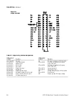
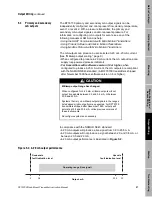
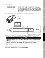
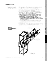
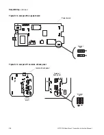
Output wiring connects to the terminals on connector CN2. Connector
CN2 is not intrinsically safe. Figure 5-1 and Table 5-1, page 26,
describe terminal designations on connector CN2, which can be
unplugged from the transmitter housing for easier installation of wiring.
• To avoid possible electrical interference, do not install output wiring in
the same conduit or cable tray as power-supply wiring or intrinsically
safe sensor wiring.
• Use individually shielded pairs of 22 AWG (0.3 mm²) or larger wires for
connections between the transmitter and any peripheral device.
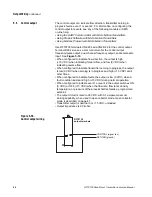
• Connect shields of twisted-pairs to terminals CN2-Z4 and/or CN2-D4.
• To comply with CENELEC standards for hazardous area installations in
Europe, nonintrinsically-safe connections between the RFT9739 and
other devices may
only
be made to devices that maintain a voltage
less than or equal to 250 V.
5.2
Maximum wire length
Currently, there is no system for accurately estimating the maximum
length of wire between the RFT9739 and a connected peripheral device.
Most applications will be able to use wire lengths up to 500 feet for
22 AWG wire (150 meters for 0.3 mm² wire), 50 feet for 28 AWG wire
(15 meters for 0.1 mm² wire), between the transmitter and any
peripheral device. However, these distances are estimates only.
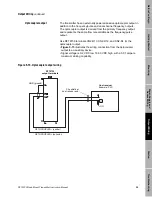
Prior to commissioning the transmitter, a loop-test is recommended as a
means for determining whether or not output signals are being received
correctly at the receiving device.
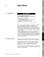
WARNING
Failure to comply with requirements for
intrinsic safety if the sensor is installed in a hazardous
area could result in an explosion.
Output wiring is not intrinsically safe.
• Keep output wiring separated from power-supply wiring
and intrinsically safe sensor wiring.
• Follow all output wiring instructions to ensure the
transmitter and any connected devices will operate
correctly.
Summary of Contents for Fisher Rosemount RFT9739
Page 1: ...Model RFT9739 Rack Mount Transmitter Instruction Manual Version 3 Transmitters February 2000 ...
Page 2: ......
Page 4: ......
Page 20: ...10 RFT9739 Rack Mount Transmitter Instruction Manual ...
Page 26: ...16 RFT9739 Rack Mount Transmitter Instruction Manual ...
Page 92: ...82 RFT9739 Rack Mount Transmitter Instruction Manual ...
Page 100: ...90 RFT9739 Rack Mount Transmitter Instruction Manual ...
Page 110: ...100 RFT9739 Rack Mount Transmitter Instruction Manual ...
Page 112: ...102 RFT9739 Rack Mount Transmitter Instruction Manual ...
Page 120: ...110 RFT9739 Rack Mount Transmitter Instruction Manual ...
Page 122: ...112 RFT9739 Rack Mount Transmitter Instruction Manual ...
Page 129: ......

