28
RFT9739 Rack-Mount Transmitter Instruction Manual
Output Wiring
continued
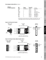
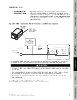
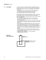
Use RFT9739 terminals CN2-D30 and CN2-Z30 for the primary mA
output. Use terminals CN2-D28 and CN2-Z28 for the secondary mA
output. See Figure 5-3.
• Primary and secondary mA output loops are isolated and floating.
Additional grounding will result in optimum performance, and optimum
HART communication on the primary mA output. Ensure that mA
output loops are grounded properly, either at the transmitter end, or at
the external device.
• The maximum allowable length for mA signal wiring is determined by
measuring resistance over the signal wires and through the receiver
device. Total loop resistance must not exceed 1000 ohms.
• The primary mA output must be set to the 4-20 mA mode for the
Bell 202 physical layer. The Bell 202 layer will not work with the primary
mA output configured as a 0-20 mA output.
• The mA output is active and cannot be converted to passive.
Figure 5-3.
Primary and secondary
mA output wiring
PV+ (signal line)
PV– (return)
SV+ (signal line)
SV– (return)
RFT9739
output terminals
PV = Primary variable
SV = Secondary variable
Summary of Contents for Fisher Rosemount RFT9739
Page 1: ...Model RFT9739 Rack Mount Transmitter Instruction Manual Version 3 Transmitters February 2000 ...
Page 2: ......
Page 4: ......
Page 20: ...10 RFT9739 Rack Mount Transmitter Instruction Manual ...
Page 26: ...16 RFT9739 Rack Mount Transmitter Instruction Manual ...
Page 92: ...82 RFT9739 Rack Mount Transmitter Instruction Manual ...
Page 100: ...90 RFT9739 Rack Mount Transmitter Instruction Manual ...
Page 110: ...100 RFT9739 Rack Mount Transmitter Instruction Manual ...
Page 112: ...102 RFT9739 Rack Mount Transmitter Instruction Manual ...
Page 120: ...110 RFT9739 Rack Mount Transmitter Instruction Manual ...
Page 122: ...112 RFT9739 Rack Mount Transmitter Instruction Manual ...
Page 129: ......


