44
RFT9739 Rack-Mount Transmitter Instruction Manual
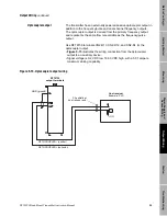
Output Wiring
continued
5.6
Peripheral device wiring
The wiring diagrams listed in Table 5-2 illustrate connections from the
transmitter to Micro Motion peripheral devices.
Table 5-2.
Peripheral wiring
diagrams
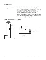
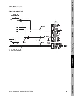
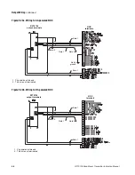
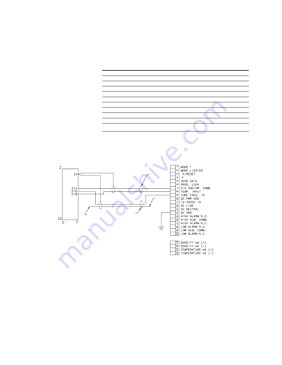
Figure 5-20. Wiring to DMS
Micro Motion peripheral device
Figure
Page
DMS Density Monitoring System
DRT Digital Rate Totalizer with LED display
DRT Digital Rate Totalizer with LCD display
FMS-3 Flow Monitoring System with LED display
FMS-3 Flow Monitoring System with LCD display
NFC Net Flow Computer
NOC Net Oil Computer with AC power supply
NOC Net Oil Computer with DC power supply
Model 3300 Discrete Controller with screw/solder terminals
Model 3300 Discrete Controller with I/O cable
Model 3350 Discrete Controller
RFT9739
output terminals
DMS
terminals
Earth
ground
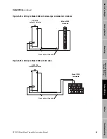
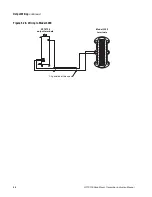
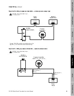
1. Clip shields at this end.
2. This wire not terminated.
Summary of Contents for Fisher Rosemount RFT9739
Page 1: ...Model RFT9739 Rack Mount Transmitter Instruction Manual Version 3 Transmitters February 2000 ...
Page 2: ......
Page 4: ......
Page 20: ...10 RFT9739 Rack Mount Transmitter Instruction Manual ...
Page 26: ...16 RFT9739 Rack Mount Transmitter Instruction Manual ...
Page 92: ...82 RFT9739 Rack Mount Transmitter Instruction Manual ...
Page 100: ...90 RFT9739 Rack Mount Transmitter Instruction Manual ...
Page 110: ...100 RFT9739 Rack Mount Transmitter Instruction Manual ...
Page 112: ...102 RFT9739 Rack Mount Transmitter Instruction Manual ...
Page 120: ...110 RFT9739 Rack Mount Transmitter Instruction Manual ...
Page 122: ...112 RFT9739 Rack Mount Transmitter Instruction Manual ...
Page 129: ......


