66
RFT9739 Rack-Mount Transmitter Instruction Manual
Startup
continued
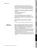
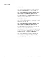
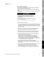
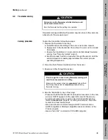
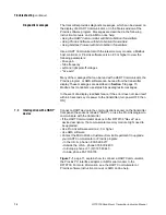
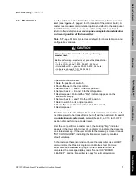
During the zeroing procedure, the display reads "Sensor OK CAL IN
PROGRESS". The default zero time will range from 20 to 90 seconds,
depending on the sensor.
After flowmeter zeroing has been completed, the mass flow rate or
volume flow rate screen reappears, and the blinking "Msg" (message)
indicator appears in the lower right corner. To clear the message
indicator, scroll past the volume inventory screen to the message
screen, which should read "Sensor OK *ERROR CLEARED*".
Diagnosing zero failure
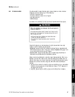
If zeroing fails, the blinking "Msg" (message) indicator appears. The
message screen will indicate the zero failure with a message such as
"*ZERO ERROR*", "*ZERO TOO HIGH*", or "*ZERO TOO LOW*". An
error condition could indicate:
• Flow of fluid during flowmeter zeroing
• Partially empty flow tubes
• An improperly mounted sensor
To clear a zeroing error, cycle power to the transmitter, ensure that the
sensor flow tubes are filled with fluid and flow is stopped, then re-zero
the flowmeter again.
Additional information
about flowmeter zeroing
Flowmeter zeroing can be disabled using the transmitter’s security
modes or with a remote (keyed) switch that disables the RFT9739 Reset
button.
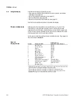
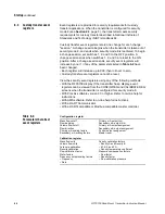
• Table 6-1 describes how RFT9739 security modes 1 through 8 affect
flowmeter zeroing. Refer to Section 2.3, page 5, for more information
about security modes.
• Section 5.11, page 58, describes how to install keyed switches to
disable the front-panel Reset button.
The transmitter has a programmable zeroing time (number of
measurement cycles), and enables the user to set the standard
deviation limits. For more information, see any of the following instruction
manuals:
•
Using the HART Communicator with Micro Motion Transmitters
•
Using ProLink Software with Micro Motion Transmitters
•
Using Modbus Protocol with Micro Motion Transmitters
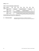
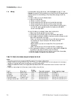
Table 6-1. Effect of security modes on flowmeter zeroing
Performed with
Mode
1
Mode
2
Mode
3
Mode
4
Mode
5
Mode
6
Mode
7
Mode
8
Reset button
Disabled
Disabled
Disabled
Disabled
Disabled
Disabled
Disabled
HART or Modbus device
Disabled
Disabled
Disabled
Disabled
Summary of Contents for Fisher Rosemount RFT9739
Page 1: ...Model RFT9739 Rack Mount Transmitter Instruction Manual Version 3 Transmitters February 2000 ...
Page 2: ......
Page 4: ......
Page 20: ...10 RFT9739 Rack Mount Transmitter Instruction Manual ...
Page 26: ...16 RFT9739 Rack Mount Transmitter Instruction Manual ...
Page 92: ...82 RFT9739 Rack Mount Transmitter Instruction Manual ...
Page 100: ...90 RFT9739 Rack Mount Transmitter Instruction Manual ...
Page 110: ...100 RFT9739 Rack Mount Transmitter Instruction Manual ...
Page 112: ...102 RFT9739 Rack Mount Transmitter Instruction Manual ...
Page 120: ...110 RFT9739 Rack Mount Transmitter Instruction Manual ...
Page 122: ...112 RFT9739 Rack Mount Transmitter Instruction Manual ...
Page 129: ......


