background image


USER MANUAL 


 m crob t


AS-1289 


Ba-AS1289-PA1

 (reparerad)


 Microbit 2.0 AB 2010. All rights reserved 


User manual 

Rev. PA1 

– 2014 feb 17 

46 of 46 


Disclaimer 
 

The author has written this document to the best of his knowledge, but does not guarantee 
that the contents will satisfy the desire and expectation of the reader. The author or Microbit 
takes no responsibility for damage or injuries of any kind that may arise from the use and 
miss use of the product or information contained. The author do not warrant the accuracy 

and 

correctness of the information contained. All brand and names mentioned are trademarks or 
registered trademarks of their respective holders. 


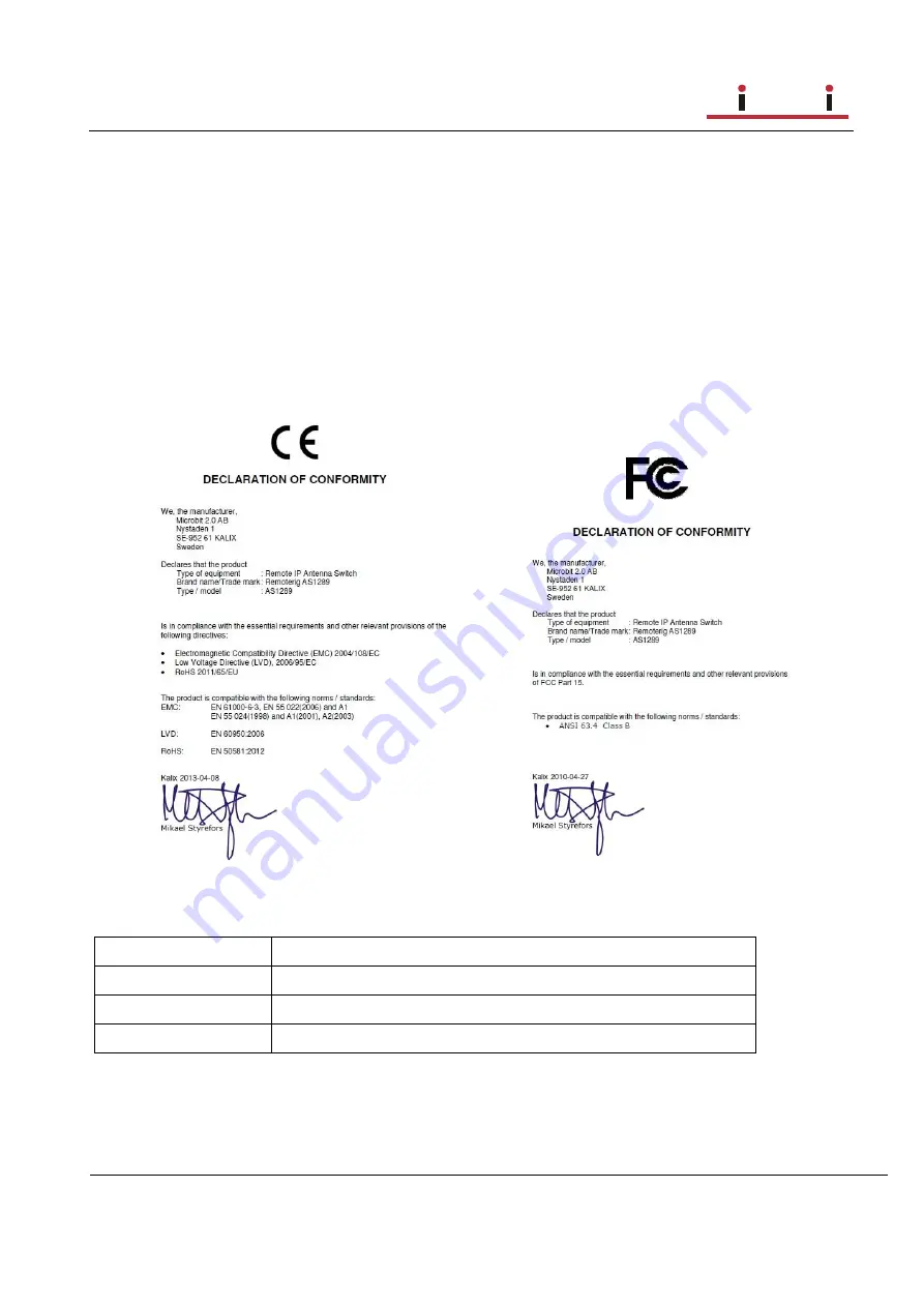
FCC / CE - Declaration of conformity 


Appendix F - Contact Information


Support site 

www.remoterig.com 

E-mail 

info@microbit.se 

Web site 

www.microbit.se 

Phone 

+46 923 69620 


Summary of Contents for AS-1289

Page 1: ...USER MANUAL m crob t AS 1289 Ba AS1289 PA1 reparerad Microbit 2 0 AB 2010 All rights reserved a User manual Rev PA1 2014 feb 17 1 of 46 AS 1289 Remote controlled Antenna switch Preliminary...

Page 2: ...guration with WEB interface 19 Set Antennas 21 Temperature RH 22 IP Settings 23 Antenna settings 26 Serial Settings 27 Advanced settings 28 Dynamic DNS setting 30 Remoterig dynamic dns service 31 DynD...

Page 3: ...to the product described in this document without notice Microbit does not assume any liability that may occur due to the use or application of the product s or circuit layout s described herein All p...

Page 4: ...itch is connected to the Internet primarily via 10 or 100 Mbit Ethernet and fixed connections like DSL cable and WLAN or 3G 4G Mobile systems The Switch is easily configured via modern USB and WEB bas...

Page 5: ...fit into your network see chapter Initial IP Setup with the Microbit Setup Manager 8 Check the installed firmware version If the one you downloaded from Remoterig is newer update the unit with the new...

Page 6: ...me to configure your remote router We recommend that you first enable the remote configuring of your router you may need it later After that s done configure port forwarding see chapter Network and Fi...

Page 7: ...46 Hardware Back On the bottom side the antenna connectors are located according to the pictures above The antenna switch is normally delivered with SO 239 jack but can also be ordered with N connecto...

Page 8: ...B cable is included with the product ETHERNET The unit can be connected to both 10 and 100 Mbit s Ethernet based TCP IP network The Antenna Switch can be configured for different connection types for...

Page 9: ...4 feb 17 9 of 46 ANT 1 5 LED A red LED indicate the selected antenna ANT5 ON LED A Green flashing LED is indicating normal status Visible through ANT5 hole LINK LED A yellow LED besides the Ethernet c...

Page 10: ...tart with downloading the Microbit Setup Manager from the homepage www remoterig com Install the Setup Manager by following the instructions which shows up If you have an older Windows version where N...

Page 11: ...PA1 2014 feb 17 11 of 46 FW HW Click on the Get button and the version of the firmware will show up in the upper window Go to the page www remoterig com and under downloads you can find the latest fi...

Page 12: ...ending on the version and release date When you have selected the file click on the Update button and the update process will start the text in the bottom field will change to Updating firmware Attent...

Page 13: ...ew window wills pop up with the basic IP settings Change the settings so they fit into your local network and press the Save button to save the new settings The Antenna switch will restart again and w...

Page 14: ...m crob t AS 1289 Ba AS1289 PA1 reparerad Microbit 2 0 AB 2010 All rights reserved a User manual Rev PA1 2014 feb 17 14 of 46 Net info Click on the Get button to read the IP setting currently in use by...

Page 15: ...1 To be able to contact the AS 1289 via the network you must configure the units to fit into your home network You can check your network configuration from your PC On the start menu select Run In the...

Page 16: ...eb 17 16 of 46 The Netmask is 255 255 255 0 the Netmask in the AS 1289 should be the same The Default gateway 192 168 0 1 the Gateway and DNS server in the Antenna Switch should be the same In this ca...

Page 17: ...t the IP of the AS 1289 must have IP s in the area 192 168 128 2 to 192 168 128 255 The Netmask is 255 255 128 0 this the Netmask in the RC should be the same The Default gateway is 192 168 128 1 the...

Page 18: ...USER MANUAL m crob t AS 1289 Ba AS1289 PA1 reparerad Microbit 2 0 AB 2010 All rights reserved a User manual Rev PA1 2014 feb 17 18 of 46...

Page 19: ...1289 If the default IP address of the Antenna Switch do not fit your network please use the PC program Microbit Setup Manager to change the IP addresses via USB Select setup page from the links on th...

Page 20: ...S1289 PA1 reparerad Microbit 2 0 AB 2010 All rights reserved a User manual Rev PA1 2014 feb 17 20 of 46 The info page shows some static information about the Antenna switch as firmware revision etc an...

Page 21: ...served a User manual Rev PA1 2014 feb 17 21 of 46 Set Antennas The Set Antenna page is the page you use for manual antenna selections If you have connected the switch a radio for automatic switching y...

Page 22: ...289 PA1 reparerad Microbit 2 0 AB 2010 All rights reserved a User manual Rev PA1 2014 feb 17 22 of 46 Temperature RH A 1 wire temp or and humidity sensor can be connected to Bus B If it s connected yo...

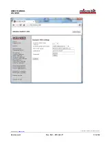
Page 23: ...u is used to setup the initial IP parameters needed for the unit to connect to the IP network Down below the settings are described more in details The Antenna switch are default configured for a DCHP...

Page 24: ...IP address is used 255 255 255 0 default nnn nnn nnn nnn Gateway Gateway only when fixed IP address is used 192 168 0 1 default nnn nnn nnn nnn Dns server DNS address only when fixed IP address is use...

Page 25: ...page user Enable password protection for the web by entering a username this field and a password next field If this field is empty the RC will not ask for password Some of the pages are still access...

Page 26: ...PA1 reparerad Microbit 2 0 AB 2010 All rights reserved a User manual Rev PA1 2014 feb 17 26 of 46 Antenna settings At the Antenna settings page you can enter a text string which describe the antenna y...

Page 27: ...tings The Antenna switch can talk direct to a radio CAT port also if the serial adapter 1216R is connected to the pin header P1 The back of the AS 1289 is prepared in advance for the installation of t...

Page 28: ...14 feb 17 28 of 46 Advanced settings On the Advanced settings page you have to select which protocol you will use depending on your radio You can select some modes which only listen and do not send an...

Page 29: ...n connection to a ICOM radio you must know the CI V Address hex the radio are set to In the example below the switch is connected to a rig with CI V address 66 The Contr Address sets the CI V address...

Page 30: ...nd DynDNS which is not free for new users anymore You can choose to use one of them The Dynamic DNS client checks what IP address your router has got from the ISP and sends the information to the Dyna...

Page 31: ...NS check interval if your IP address change often you can select a low value if it goes month between the changes you can select a higher value After that click on Submit and Apply changes the AS 1289...

Page 32: ...USER MANUAL m crob t AS 1289 Ba AS1289 PA1 reparerad Microbit 2 0 AB 2010 All rights reserved a User manual Rev PA1 2014 feb 17 32 of 46...

Page 33: ...ate more than one DynDNS client at the same LAN segment DynDNS do not accept multiple updates from same IP The DynDNS client checks what IP address your router has got from the ISP and sends the infor...

Page 34: ...ss of your router should be checked value in minutes Off Dynamic DNS client disabled 10 20 30 40 50 60 180 600 1440 Dynamic DNS host name Sets which DNS service you will use ddns remoterig com our own...

Page 35: ...nction which can be used as an extra security This function is quite common in network equipment It can be set to ping an IP address and when it does not get any answer it will make a hard reboot of t...

Page 36: ...an be used for test Yes reboot Function is enabled IP address to ping IP address to ping is entered here In normal cases use the Gateway IP Ping Interval seconds Interval between the ping is sent 1 65...

Page 37: ...014 feb 17 37 of 46 Radio RRC Settings At the Radio RRC settings page you setup the connection to the Radio RRC if you want the Antenna switch to talk to the radio via the RRC Note the RRC must be con...

Page 38: ...at different frequencies First select which antennas you want to be automatically selected on the bottom line Then you can enter the frequency ranges in the boxes to the left ant mark which antenna p...

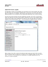
Page 39: ...ike 1216H CRC_v4 01_2014 01 04 bin Connect to the Antenna switch and select Application upgrade Then click on the Browse button and select the file with the new firmware After that you click on the Up...

Page 40: ...Rev PA1 2014 feb 17 40 of 46 Bootloader firmware upgrade This follows the same steps as the application firmware upgrade procedure above Restart device Restart device can be used if you want to reset...

Page 41: ...so that port 80 default settings is directed to the Antenna switch which should have a static IP address If you have other remote controlled equipment connected to the router port 80 is probably alrea...

Page 42: ...10 All rights reserved a User manual Rev PA1 2014 feb 17 42 of 46 Portforwarding A typical setup screen for activating port forwarding is shown below There is one row assigned for each port service al...

Page 43: ...USER MANUAL m crob t AS 1289 Ba AS1289 PA1 reparerad Microbit 2 0 AB 2010 All rights reserved a User manual Rev PA1 2014 feb 17 43 of 46...

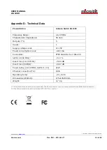
Page 44: ...pply voltage Local 12 15V Power consumption Local 200 mA Connectors PTFE dielectric N or SO 239 SWR 1 8 50 MHz 1 17 1 Insert loss 1 8 30 MHz 0 04 dB Insert loss 50 MHz 0 07 dB Power rating 1 8 30 MHz...

Page 45: ...e to radio or television reception which can be determined by turning the equipment off and on the user is encouraged to try to correct the interference by one or more of the following measures Reorie...

Page 46: ...The author or Microbit takes no responsibility for damage or injuries of any kind that may arise from the use and miss use of the product or information contained The author do not warrant the accura...

Reviews: