USER MANUAL
m crob t
AS-1289
Ba-AS1289-PA1
(reparerad)
Microbit 2.0 AB 2010. All rights reserved
a
User manual
Rev. PA1
– 2014 feb 17
7 of 46
Hardware
Back
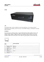
On the bottom side the antenna connectors are located according to the pictures above. The
antenna switch is normally delivered with SO-239 jack but can also be ordered with N
connectors.
Power
The Antenna switch should be powered via the 2.1/5.5 DC jack on the back of the AS1289.
Pin no
PWR
+
+ 12-15VDC (centre)
-
GND
12V DC


