background image


USER MANUAL 


 m crob t


RRC-1258 MKII 


Ba1258B_RemoteRig_MkIIs-A30 


 Microbit 2.0 AB 2010. All rights reserved 


User manual 

Rev. A30 

– 2014 Jan 21 

214 of 228 


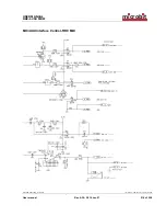
MIC/AUX Interface Control-RRC MkII 


Summary of Contents for RRC-1258 MkII

Page 1: ...R MANUAL m crob t RRC 1258 MKII Ba1258B_RemoteRig_MkIIs A30 Microbit 2 0 AB 2010 All rights reserved a User manual Rev A30 2014 Jan 21 1 of 228 RRC 1258 MkII s Yaesu Twin Elecraft K3 Twin etc User Man...

Page 2: ...info 30 WiFi and Serial Port tabs 30 Initial IP setup 31 Configuration with WEB interface 34 Info 35 Status 36 Profiles 38 IP Settings 40 Radio Settings 43 Serial Settings 49 Advanced settings 56 Dyna...

Page 3: ...100 101 General 101 Hardware configuration 101 Radio settings example 102 Connections 102 Power supply 103 ICOM IC 703 IC 706 104 General 104 Hardware configuration 104 Radio settings example 105 Conn...

Page 4: ...example 136 Connections 137 Logging or computer control RTTY etc 139 YAESU FT 857 145 General 145 Hardware configuration 145 Connections 147 Power supply 147 YAESU FTM 350 150 General 150 Hardware co...

Page 5: ...Hardware configuration 184 Radio settings example 185 Power supply 185 KENWOOD TS 2000 188 General 188 Hardware configuration 188 Radio settings example 189 Connections 189 ELECRAFT K3 Twin 193 Genera...

Page 6: ...nterface Control RRC MkII 214 Speaker output interface Control RRC MkIIs 215 Speaker input interface Radio RRC MkIIs 215 MIC AUX Interface Radio RRC 216 Networks and Firewalls 217 DMZ 218 Portforwardi...

Page 7: ...anges to the product described in this document without notice Microbit does not assume any liability that may occur due to the use or application of the product s or circuit layout s described herein...

Page 8: ...emoterig system fits very well in the following situations You are not allowed to put up antennas at your home The noise level is too high to make Amateur radio activity possible You want to build so...

Page 9: ...replace the cable between the control panel and the radio with the Remoterig system You will get the same feeling and functionality as with the original setup TWIN The twin solution for Elecraft K3 a...

Page 10: ...User manual Rev A30 2014 Jan 21 10 of 228 PC based control The system also works very well for more traditional remote control from PC based control software s like HamRadioDeLuxe The Remoterig syste...

Page 11: ...g their resp IP address If you get in contact with their internal web server everything is OK 8 Disconnect all cables from the units and open the housings see chapter Strappings and jumpers and make t...

Page 12: ...about Dynamic DNS services see the Dynamic DNS chapters under Configuration with WEB Interface 16 After moving the RRC apart you need to connect a PC to the local network at the remote site where the...

Page 13: ...eters It can also be used for downloading new software can also be done via the WEB interface At the Control RRC it can also be used for CAT control PTT RTTY or CW control via the RTS and DTR signals...

Page 14: ...us LED LED Red LED Yellow Off Incoming audio stream OK SIP disconnected Flashing SIP connection failed On Incoming audio stream fail SIP connection OK Pin no AUX RJ45 1 depends on the inside straps 2...

Page 15: ...e mini DIN connector The connector is configured so a straight cable can be used to a TS 480 control panel and to RC 2000 Pin no AUX RJ45 6 AF Input TS 480 5 TDO input data to radio TTL 4 RDO output d...

Page 16: ...input for the speaker signals from the radio The Dual Rx version has inputs for both the Main Rx and Sub RX The Main Rx input is connected in parallel with the input pins in the MIC AUX and TTL conne...

Page 17: ...cable between RRC and PC The communication parameter is set via the web interface Pin no RS 232 Interface for PC connection 9 pol D sub female 1 2 RXD out to PC RXD 3 TXD in from PC TXD 4 5 GND 6 7 R...

Page 18: ...is connected to the tip and the right paddle to the ring Common is connected to the inner ring and ground Note that the CW Keyer function must be enabled to activate this function PAD Radio RRC At the...

Page 19: ...168 0 1 I O In the I O connector is 3 2 inputs and 3 outputs 8V and GND available see below The connector is used for transferring signals from one RRC to the other If the CW keyer function is not us...

Page 20: ...s Ethernet based TCP IP network The RRC can be configured for different connection types for Ethernet port Auto 10HDX 10FDX 100HDX 100FDX and Auto with preferred 10FDX Default is Auto with preferred...

Page 21: ...you need to put some straps in place depending on your radio Down below follows instructions of how to disassembly the RRC and pictures showing where to find the different straps 1 Start with removing...

Page 22: ...ccording to the description for the radio see radio chapter Normally the same strapping should be done in both Control RRC and Radio RRC The picture shows the strapping for IC 706 Attention The strapp...

Page 23: ...panels should be 8 or 9 V With the strap in place it will be 8V which fits all ICOM radios Without the strap the voltage will be 9V which fits Kenwood TS 480 and RC 2000 panels that need 9V for the b...

Page 24: ...IIs up to Hardware version 5 JMP 4 is used to select between Speaker level or Headset level for the Main Rx output The Sub Rx is always Headset level From hardware version 6 it s always speaker level...

Page 25: ...B_RemoteRig_MkIIs A30 Microbit 2 0 AB 2010 All rights reserved a User manual Rev A30 2014 Jan 21 25 of 228 9 When you are done you can slide the lid on the bottom part and put back the screws Be caref...

Page 26: ...nd WiFi setup Start with downloading the Microbit Setup Manager from the homepage www remoterig com Install the Microbit Setup Manager by following the instructions which shows up If you have an old v...

Page 27: ...HW version When you connect the RRC the version of the firmware and Bootloader will show up in the upper window The hardware versions is also shown Go to the page www remoterig com and under downloads...

Page 28: ...7 bin depending on the version and release date When you have selected the file click on the Update button and the update process will start the text in the bottom field will change to Updating firmwa...

Page 29: ...ct the profile from v2 44 More info about the IP setup see Initial IP setup A new window wills pop up with the basic IP settings Change the settings so they fit into your local network and press the S...

Page 30: ...s reserved a User manual Rev A30 2014 Jan 21 30 of 228 Net info Click on the Get button to read the IP setting currently in use by the RRC WiFi and Serial Port tabs The Wifi tab is described in the Wi...

Page 31: ...d the gateway 192 168 0 1 To be able to contact the RRC units via the network you must configure the units to fit into your home network You can check your network configuration from your PC On the st...

Page 32: ...in this example is 192 168 128 10 this means that the IP of the RRC s must have IP s in the area 192 168 128 2 to 192 168 128 255 The Netmask is 255 255 128 0 this the Netmask in the RRC S should be...

Page 33: ...USER MANUAL m crob t RRC 1258 MKII Ba1258B_RemoteRig_MkIIs A30 Microbit 2 0 AB 2010 All rights reserved a User manual Rev A30 2014 Jan 21 33 of 228...

Page 34: ...C If the default IP addresses of the RRC not fit your network please use the PC program Microbit Setup Manager to change the IP addresses via USB It s convenient to use DHCP at the Control RRC but wai...

Page 35: ...a1258B_RemoteRig_MkIIs A30 Microbit 2 0 AB 2010 All rights reserved a User manual Rev A30 2014 Jan 21 35 of 228 Info The info page shows some static information about the RRC as firmware revision etc...

Page 36: ...n some modes If the system is setup to be used with Control panels or Twins then there is no Connect disconnect buttons the connection is controlled by the power on switch on the control panel In some...

Page 37: ...USER MANUAL m crob t RRC 1258 MKII Ba1258B_RemoteRig_MkIIs A30 Microbit 2 0 AB 2010 All rights reserved a User manual Rev A30 2014 Jan 21 37 of 228...

Page 38: ...ften But NO settings are needed here if you do not use it so leave this page to later if it s your initial setup of the RRC s You can use up to five profiles and you can give them describing names The...

Page 39: ...ge profile just select Active profile to the profile you want to change to and press submit The new profile will then be loaded but will not be used before restart so you can check all settings and th...

Page 40: ...Microbit 2 0 AB 2010 All rights reserved a User manual Rev A30 2014 Jan 21 40 of 228 IP Settings The IP Settings menu is used to setup the initial IP parameters needed for the unit to connect to the I...

Page 41: ...28 default Radio RRC nnn nnn nnn nnn Netmask Net mask only when fixed IP address is used 255 255 255 0 default nnn nnn nnn nnn Gateway Gateway only when fixed IP address is used 192 168 0 1 default nn...

Page 42: ...i even if the Ethernet is not available for the moment Auto prefer Ethernet default Ethernet Web page user Enable password protection for the web pages and also the telnet connection by entering a use...

Page 43: ...10 All rights reserved a User manual Rev A30 2014 Jan 21 43 of 228 Radio Settings The Radio settings are used to setup the RRC to act together with different radios The settings must be done in both C...

Page 44: ...USER MANUAL m crob t RRC 1258 MKII Ba1258B_RemoteRig_MkIIs A30 Microbit 2 0 AB 2010 All rights reserved a User manual Rev A30 2014 Jan 21 44 of 228...

Page 45: ...0 FT 2K FT 5K FT 9K Twin 11 Transparent 4 wire for repeater links etc 12 DX SR8 with detached control panel 13 ID E880 with detached control panel 14 K3 twin 15 Yaesu FT 857 with detached control pane...

Page 46: ...bits 16 kHz 9 A law 24 kHz 10 Linear 12 bits 24 kHz 11 Linear 16 bits 24 kHz 12 IMA ADPCM 4 bits 8 kHz 12 IMA ADPCM 4 bits 16 kHz Audio Dual RX Sets if LF from the Sub RX should be sent as an separate...

Page 47: ...les a 20 dB pre amplifier for the audio input at the Control RRC No Yes default Codec inp attenuation Radio RRC Enables a 20 dB attenuator to the speaker input at the Radio RRC No default Yes COM0 bau...

Page 48: ...ould be 2 and works for all radios except FT 1000 in 4800 baud which need it to be set to 60 2 default 60 FT 1000 in 4800 baud Use USB Com Port as COM0 COM0 can be connected to the USB interface inste...

Page 49: ...also a COM3 which is only available via USB and only for WinKey and RTTY Radio settings Program mode COM1 free channel COM2 free channel 0 Transparent yes yes 1 ICOM CI V yes no 2 IC 7100 IC 706 IC 70...

Page 50: ...USER MANUAL m crob t RRC 1258 MKII Ba1258B_RemoteRig_MkIIs A30 Microbit 2 0 AB 2010 All rights reserved a User manual Rev A30 2014 Jan 21 50 of 228...

Page 51: ...packet is send for each char needs lot of bandwidth Mode 2 ICOM CI V Used for CI V control of IC 703 706 at the same time as you use the control panel Mode 3 Char timeout A data packet is sent when t...

Page 52: ...rom control side COM2 and local COM1 will be intelligent mixed in sequence before sent to local COM2 Data from local COM2 goes to both local COM1 and to the control side COM2 via IP Can be used for Mi...

Page 53: ...output of other RRC 0 No default 1 Yes COM1 terminator Defines the terminator character used in COM1 mode 5 user def terminator Character should be in HEX format 00 default Use USB Com Port as COM1 C...

Page 54: ...if you want to define the terminator char by yourself see below Mode 8 The WinKeyer emulator is activated and data received from COM1 are sent as CW from the Radio RRC in parallel with the ordinary ke...

Page 55: ...USER MANUAL m crob t RRC 1258 MKII Ba1258B_RemoteRig_MkIIs A30 Microbit 2 0 AB 2010 All rights reserved a User manual Rev A30 2014 Jan 21 55 of 228...

Page 56: ...here are more than one RRC on your LAN In earlier versions we used port 5060 for SIP but it s often reserved for IP telephony today so we have changed default ports You really need to know what you ar...

Page 57: ...10 All rights reserved a User manual Rev A30 2014 Jan 21 57 of 228 Parameter Setting UDP cmd port Port number used for the Command channel 13002 default UDP audio port Port number used for the audio c...

Page 58: ...acket size ms Sets the max size length of the audio packets in ms If you have a good Internet connection with lots of bandwidth or running both RRC s under the same LAN WLAN it s possible to reduce th...

Page 59: ...itch on and off Yaesu FT 450 950 2000 5000 9000radios automatically on connect disconnect when radiomode 4 or 10 is used No default Yes PTT off mute delay Control RRC only Makes it possible to mute ch...

Page 60: ...ur remote router you only need to remember the own host name The Radio RRC will automatically update the DNS server when the IP changes so you don t need to bother about it Remoterig dynamic dns servi...

Page 61: ...ortant information is the Own hostname copy the whole row this is the information you should put into the SIP contact box in the Control RRC and the web address you should use when remote configure th...

Page 62: ...setup and restarted the RRC it will update the Remoterig DDNS You can check the status of the update at http ddns remoterig com status Enter the hostname from your RRC in this example hfd3dqw6 If your...

Page 63: ...e than one DynDNS client at the same LAN segment DynDNS do not accept multiple updates from same IP The DynDNS client checks what IP address your router has got from the ISP and sends the information...

Page 64: ...address of your router should be checked value in minutes Off Dynamic DNS client disabled 10 20 30 40 50 60 180 600 1440 Dynamic DNS host name Sets which DNS service you will use ddns remoterig com o...

Page 65: ...and jitter caused by Internet in a unique way This function is also dependent on the I O configuration see IO settings The Keyer also handles straight key CW generated from an old fashion straight key...

Page 66: ...Hz default 0 No local side tone is generated can be used to test how the CW sounds if you enable side tone in the radio and send with memory keyer or PC Side tone dB Audio level for the side tone in d...

Page 67: ...le PTT activated by keyer is a function that is useful if you want the PTT input of the radio to be activated when using the Remoterig keying function The PPT is activated before the Key delay meaning...

Page 68: ...0 AB 2010 All rights reserved a User manual Rev A30 2014 Jan 21 68 of 228 Parameter Setting PTT activated by keyer Enable the PTT function No default Yes PTT is activated by the keyer PTT tail delay...

Page 69: ...IO Settings The inputs and outputs in both the Control RRC and Radio RRC are configurable to meet different needs Control RRC Parameter Setting IN0 mode Select the function for Input 0 IN0 signal in...

Page 70: ...igured for one oftwo functions I O The output follows Input 2 from the Radio RRC Keyer The output follows the Keyer output USB RTS as PTT Select which of the USB virtual COM ports RTS signal which sho...

Page 71: ...USER MANUAL m crob t RRC 1258 MKII Ba1258B_RemoteRig_MkIIs A30 Microbit 2 0 AB 2010 All rights reserved a User manual Rev A30 2014 Jan 21 71 of 228 Radio RRC...

Page 72: ...tive 4 On Off controlled by the ON OFF button on this side 5 Keyer PTT active when CW is send via the keyer can be used to key a PA If you set key delay in the Control RRC this output will be activate...

Page 73: ...hecked at the status page This function is only available on the Radio RRC Enable ping watchdog Enables the function No Function is disabled Yes test Function enabled but it will not actually reboot c...

Page 74: ...KII Ba1258B_RemoteRig_MkIIs A30 Microbit 2 0 AB 2010 All rights reserved a User manual Rev A30 2014 Jan 21 74 of 228 Wi Fi settings You can enter SSID and Password direct or check them on the WiFi pag...

Page 75: ...file with the actual settings and status of the unit This file can be sent via email for support purposes for example Export settings bin This function is used to backup your settings to a file in you...

Page 76: ...rights reserved a User manual Rev A30 2014 Jan 21 76 of 228 Import settings bin This function is used import your backup file from your PC Click on select file and browse to your file and then click...

Page 77: ...ame like RRC1258 CRC_v1 38_2009 09 04 bin Connect to the RRC you want to update and select Application upgrade Then click on the Browse button and select the file with the new firmware After that you...

Page 78: ...ser manual Rev A30 2014 Jan 21 78 of 228 Bootloader firmware upgrade This follows the same steps as the application firmware upgrade procedure above Restart device Restart device can be used if you wa...

Page 79: ...ngs 38400 baud 8 bits No parity and 1 stop bit Select the sys s and setup edit 1 menus to configure the RRC This method of configuration is not user friendly and should be avoided a audio c codec d de...

Page 80: ...Control RRC the main reason to use WiFi might be the portability and for the Radio RRC to physically separate the RRC from the telephone DSL line which is the most common route for lightning storms t...

Page 81: ...WiFi connection is to do it via the Microbit Setup manager If you know the parameters it can be done from the web interface also but you cannot scan WiFi Networks that way so we focus on using the Se...

Page 82: ...Microbit 2 0 AB 2010 All rights reserved a User manual Rev A30 2014 Jan 21 82 of 228 Click on the Get button You will get a empty page when the unit is not programmed when you later open this page you...

Page 83: ...2010 All rights reserved a User manual Rev A30 2014 Jan 21 83 of 228 After a 1 second you will see the WiFi networks which are available at your current location The networks are sorted in order decid...

Page 84: ...erved a User manual Rev A30 2014 Jan 21 84 of 228 Select the network you want to use by clicking on the button beside the SSID Click on the button on the row where you want to store the Network Click...

Page 85: ...anual Rev A30 2014 Jan 21 85 of 228 Give The RRC a few seconds to reboot and connect to the WiFi Network Click on the Net info tab Click on the Get button You will now see that the Box has got an IP a...

Page 86: ...lick on the Browse unit button You will now see the RRC internal web pages 1 Click on Info and you will see the WiFi network status 1 Your PC has to be connected to the same network as the RRC if it s...

Page 87: ...the ping time between control and radio QTH Another unique feature is a kind of adjustable jitter buffer at the radio end If the Internet connection has varying latencies you can set a key delay befor...

Page 88: ...o available in the I O connector Signal PAD jack IO setting keyer output tip OUT2 mode Keyer keyer output ring OUT1 mode Keyer gnd inner ring USB Control RRC A PC with straight key functionality can b...

Page 89: ...IO setting right paddle 1 IN1 left paddle 2 IN2 straight key PC 4 IN0 IN0 mode Keyer gnd 8 I O connector Radio RRC The output signal from the CW keyer to the radio straight KEY input can also be foun...

Page 90: ...K audio frequency shift keying since you don t need to set mic gain and other settings The RRC 1258 has a separate serial channel for transfer of 45 45 baud RTTY keying data The RTTY serial channel is...

Page 91: ...s A30 Microbit 2 0 AB 2010 All rights reserved a User manual Rev A30 2014 Jan 21 91 of 228 At the Radio RRC IO settings page you need to select which output you want to use for the RTTY keying signal...

Page 92: ...ts reserved a User manual Rev A30 2014 Jan 21 92 of 228 RTTY with MMTTY The Remoterig specific settings to use MMTTY for RTTY is shown below At the TX tab select the PTT FSK comport to the same compor...

Page 93: ...AL m crob t RRC 1258 MKII Ba1258B_RemoteRig_MkIIs A30 Microbit 2 0 AB 2010 All rights reserved a User manual Rev A30 2014 Jan 21 93 of 228 At the Misc tab e select COM TxD FSK and click on the USB Por...

Page 94: ...Jan 21 94 of 228 In the USB port option dialog select C limiting speed If not limiting speed is selected the PTT will be released before the whole RTTY string is sent because the USB communication is...

Page 95: ...eyer output tip keyer output ring OUT1 mode Baudot 45 gnd inner ring USB Control RRC A PC with a suitable software like MMTTY can be used to perform the RTTY keying Together with the RTTY keying signa...

Page 96: ...radio Then you have to use a PC software e g HamRadioDeLuxe or similar rig control software at the control site All audio and data communication goes true the RRC s and you don t need a PC at the remo...

Page 97: ...Auto connect No Audio quality 2 Linear 16 bits 8 kHz 2 Linear 16 bits 8 kHz Audio dual rx No Codec out gain 255 255 Codec inp gain 18 0 Codec inp preamp Yes Codec inp HPF Hz 163 163 COM0 baudrate 9600...

Page 98: ...connector to the radios CI V jack you can use the Remoterig I11c cable or make it by your self The cable should have a 4 6 modular connector in one end and a 3 5 mm stereo plug in the other end The 3...

Page 99: ...1258 Cable I10 1 1 Generic ICOM cables RRC 1258MkII 1 2 m crob t 8 pol RJ 45 Con Mic Inp 8 pol Circular male I10a screened 20 cm 7 5 1 6 6 7 5 3 8 3 4 GND GND MIC MIC MICE MICE PTT PTT 1 2 2 8V 8V UP...

Page 100: ...ICOM cables RRC 1258MkII 1 2 m crob t Front panel view 1 8 TTL 4 6 modular 1 2 3 4 5 6 7 8 SPEAKER 3 5 mm stereo plug SPEAKER 3 5 mm stereo plug CI V 3 5 mm stereo plug 1 2 5 6 3 4 1 6 GND TDO RDO I11...

Page 101: ...remote functionality from the control panel and the feeling is exactly as if you use them locally It s one of the simplest rig to setup and come on the air with No special cables needed just connect...

Page 102: ...rate 38400 38400 COM0 data bits 8 8 COM0 stop bits 1 1 COM0 parity 0 Off 0 Off Available only in RRC 1258MkIIs Connections All necessary signals between the panel and the radio are connected via the 8...

Page 103: ...228 Power supply Control RRC The Control RRC is supplied with a common 13 8 V 10 18V power supply The display and speaker amplifier needs a lot of power so you need 1A Radio RRC The Radio RRC should b...

Page 104: ...ling IC 703 706 is simple it s just to extend the cord between the radio and the control panel using Internet When you press the power button on the panel the radio comes to life at the remote side an...

Page 105: ...epresented in the cable the numbering is for the RJ45 connector to the RRC after converting the cable not for the ICOM connector 1 8V power to control panel only when radio is ON 2 LRXD serial data 19...

Page 106: ...of 228 Power supply Control RRC The Control RRC is supplied with a common 13 8 V 10 18V power supply The display and speaker amplifier needs a lot of power so you need 1A Radio RRC The Radio RRC shou...

Page 107: ...3 3 4 4 4 4 Yellow Yellow Green White Green White Blue Blue Brown Brown Black Black Green Green Blue Blue Orange Orange Orange White Orange White Red Red Blue White Blue White Screen to Red Screen to...

Page 108: ...reserved a User manual Rev A30 2014 Jan 21 108 of 228 Prepare the separation cable to IC 703 and IC 706 The cable between front and radio before it is cut apart You have to buy this cable from your lo...

Page 109: ...white has a green shield The shielded white wire is thinner than the white one without a shielding That way you can identify them from each other The outer shielding is not connected to the RRC Cut al...

Page 110: ...nking tube to each wire Cut them short enough so they don t shrink from the heat of the solder iron First tread a 100 mm long 6 4 mm shrinking tube on the separation cable Then tread a 80 mm long 6 4...

Page 111: ...me with the other part The one with the connector to the control panel When you have finished both cables connect them together with the supplied RJ45 extender Check the cable with an ohm meter You sh...

Page 112: ...R ON button an audio and data connection is established between the units and you control the receiver as you do normally with the control panel attached directly to the receiver Hardware configuratio...

Page 113: ...simple and can be done with simple RJ connectors Power supply Control RRC The Control RRC is supplied with a common 13 8 V 10 18V power supply The display and speaker amplifier needs a lot of power so...

Page 114: ...User manual Rev A30 2014 Jan 21 114 of 228 1258 Cable I14 1 1 ICOM cable RRC 1258MkII to IC R2500 Panel end 1 2 m crob t HV HV GND GND PWR SW PWR SW TDO TDO RDO RDO Control Panel IC R2500 1 1 1 2 2 5...

Page 115: ...ev A30 2014 Jan 21 115 of 228 1258 Cable I15 1 1 ICOM cable RRC 1258MkII to IC R2500 Radio end 1 2 m crob t RRC 1258MkII MIC AUX 8 pol Modular Con SPEAKER 3 5 mm stereo plug SPEAKER 3 5 mm stereo plug...

Page 116: ...ntrol panel and the radio with two RRC 1258 units one at the control panel and one at the radio When you push the PWR ON button an audio and data connection is established between the units and you co...

Page 117: ...TTL connector Mark up the cable so you connect the connectors to the right unit it will not work if you try to use it connected backwards The microphone can be connected direct to the RRC AUX MIC conn...

Page 118: ...ing sockets which means that no red straps are needed The pcb with the yellow cable are mounted in the Control RRC and the pcb with the blue cable are mounted in the Radio RRC The yellow and blue cabl...

Page 119: ...USER MANUAL m crob t RRC 1258 MKII Ba1258B_RemoteRig_MkIIs A30 Microbit 2 0 AB 2010 All rights reserved a User manual Rev A30 2014 Jan 21 119 of 228 Control RRC Radio RRC...

Page 120: ...of 228 Power supply Control RRC The Control RRC is supplied with a common 13 8 V 10 18V power supply The display and speaker amplifier needs a lot of power so you need 1A Radio RRC The Radio RRC shou...

Page 121: ...s reserved a User manual Rev A30 2014 Jan 21 121 of 228 1258 Cable I13 1 1 ICOM cable RRC 1258MkII to IC 2820 Panel end 1 2 m crob t 8V GND TDO RDO Control Panel IC E2820 1 4 4 pol Modular 2 4 I13a 3...

Page 122: ...IC E2820 Radio end 1 2 m crob t Mic Inp IC E2820 Control Inp IC E2820 RRC 1258MkII RRC 1258MkII 1 2 3 5 5 6 4 3 2 4 8V GND TDO RDO 8 pol RJ 45 Con 4 6 pol Modular Con 4 6 pol Modular Con 8 pol RJ 45 C...

Page 123: ...th the control panel directly attached to the radio Hardware configuration If you have a RRC with harware v7 or later the setup is simple for hardwares before v7 the prepararions is a little bit more...

Page 124: ...cted backwards The microphone can be connected direct to the RRC AUX MIC connector if you have a microphone with RJ 45 connector The speaker is connected direct to the RRC SP jack with a 3 5 mm stereo...

Page 125: ...re mounted in the Control RRC and the pcb with the blue cable are mounted in the Radio RRC The yellow and blue cables need to be solder to one point on the RRC pcb See pictures below Be sure to remove...

Page 126: ...28 Radio RRC Power supply Control RRC The Control RRC is supplied with a common 13 8 V 10 18V power supply The display and speaker amplifier needs a lot of power so you need 1A Radio RRC The Radio RRC...

Page 127: ...t Control Inp ID E880 RRC 1258MkII 1 2 3 5 5 6 6 4 3 2 1 4 8V PWR ON GND GND TD RD 6 6 pol Modular Con 6 6 pol Modular Con I21b I21c 1 6 1 6 SPEAKER 3 5 mm stereo plug SPEAKER 3 5 mm stereo plug Whit...

Page 128: ...an 21 128 of 228 1258 Cable I22 1 1 ICOM cable RRC 1258MkII to ID E880 Panel end RRC v7 1 2 m crob t Control Panel IC E880 1 6 6 pol Modular RRC 1258MkII TTL 6 pol Modular Con 1 6 SPEAKER 3 5 mm stere...

Page 129: ...udio and data connection is established between the units and you control the radio as you do normally with the control panel directly attached to the radio There are no limitations in functionality e...

Page 130: ...ser manual Rev A30 2014 Jan 21 130 of 228 Radio side Microbit Adapters 1258L When assembling the adapter pcb s take notice that they are not the same in the different units one is marked Control and t...

Page 131: ...18 0 Codec inp preamp Yes Codec inp HPF Hz 163 163 COM0 baudrate 9600 9600 COM0 data bits 8 8 COM0 stop bits 1 1 COM0 parity 0 Off 0 Off Available only in RRC 1258MkIIs remember that the bandwidth dem...

Page 132: ...reserved a User manual Rev A30 2014 Jan 21 132 of 228 1258 Cable I18 1 1 ICOM cable RRC 1258MkII to IC 2725 Panel end 1 2 m crob t 1 6 Control Panel IC 2725 6 1 5 2 2 5 1 6 7 8 4 3 3 4 6 pol Modular R...

Page 133: ...r manual Rev A30 2014 Jan 21 133 of 228 1258 Cable I17 1 1 ICOM cable RRC 1258MkII to IC 2725 Radio end 1 2 m crob t RRC 1258MkII MIC AUX 8 pol Modular Con SPEAKER 3 5 mm stereo plug SPEAKER 3 5 mm st...

Page 134: ...n All you need to do is to put the system together and do the IP settings The twin concept is mainly developed for using with two radios of the same model for example two FT 5000 but two different mod...

Page 135: ...ads to the corresponding antenna ports on the control radio As the radio do not use full power when tuning and it s done relatively fast small and cheap 10 20W dummy loads can be used not included Har...

Page 136: ...twin SIP password hello hello SIP contact 192 168 0 228 Auto connect No Audio quality 2 Linear 16 bits 8 kHz 2 Linear 16 bits 8 kHz Audio Dual RX Yes 1 Codec out gain 255 255 Codec inp gain 18 0 Codec...

Page 137: ...y to the PWR jack 2 Connecter Ethernet to the Ethernet jack 2m CAT 5 cable included 3 Connect the CAT cable Y5d from the COM2 connector to the radio CAT connector 4 Connect the microphone via the Micr...

Page 138: ...et to the Ethernet jack 2m CAT 5 cable included 3 Connect the CAT cable Y6d from the COM2 connector to the radio CAT connector 4 Connect the mic cable Y6a from the AUX MIC jack to the radio mic connec...

Page 139: ...you need to connect a antenna switch for example which need to talk to the remote Radio you can connect it to the Radio RRC COM1 and configure COM1 to Mode 6 CAT to COM2 local If you want to connect a...

Page 140: ...0 of 228 Cable Y5d Control Radio to Control RRC COM2 Cable Y6d Radio RRC to Remote Radio COM2 Cable Y5a Mic to Control RRC Mic jack Cable Y6a Radio RRC Mic jack to Radio Mic input Cable 3 5 mm 3 5 mm...

Page 141: ...one can be connected direct to the RRC AUX MIC connector if you have a microphone with RJ 45 connector If you have a microphone with a circular connector use the adapter cable Y5a The speaker is conne...

Page 142: ...t jack or similar to the Radio RRC SP jack with the standard 3 5 mm 3 5 mm cable with stereo plugs in both ends If the radio have a jack use the supplied adapter to 3 5mm Connect keyer cable standard...

Page 143: ...e Y5 1 1 YAESU TWIN Cables RRC 1258MkII to Radio twin Control side 1 2 m crob t FT 950 2000 5000 9000 CAT port RRC 1258MkII 3 3 5 7 7 8 8 5 2 2 DSUB 9pol Female DSUB 9pol Male Front panel view 1 2 3 4...

Page 144: ...YAESU TWIN cables RRC 1258MkII Radio twin radio side 1 2 m crob t Radio CAT port 3 5 2 GND DSUB 9pol Female 8 8 7 7 3 5 2 DSUB 9pol Female GND GND PTT PTT MIC MIC MICE Y6a Y6b MICE RRC 1258MkII RRC 1...

Page 145: ...also be used but then some hardware changes or special cabling are needed See at the website under Support and Mods If you have a set of RRC s hardware 7 or later you only need to make cables The cabl...

Page 146: ...are only valid for RRC s from hardware version 7 Also remember to remove JMP 5 in both the control and radio RRC Radio settings example Parameter Control Radio Program mode 15 FT 857 15 FT 857 SIP pa...

Page 147: ...ophone can be connected direct to the RRC AUX MIC connector The speaker is connected direct to the RRC SP jack with a 3 5 mm stereo plug or to the FT 857 front panel speaker jack Radio RRC The control...

Page 148: ...DRAWING NR REPLACE SCAL E OK STAND CHECKED COPIED DRAWN CON STR REPLACED BY NOTE DIMENSION NAME CNT DET NR DATE MS 1258 Cable Y9 1 1 YAESU FT 857 Cable Contr panel RRC 1258MkII 120124 1 2 m crob t 1 1...

Page 149: ...EPLACED BY NOTE DIMENSION NAME CNT DET NR DATE MS 1258 Cable Y9 1 1 YAESU FT 857 cable RRC 1258MkII Radio 120124 1 2 m crob t FT 857 MIC RRC 1258MkII AUX MIC 1 1 1 1 1 1 8 6 8 pol RJ 45 Con 8 pol RJ 4...

Page 150: ...en you push the PWR ON button an audio and data connection is established between the units and you control the radio as you do normally with the control panel directly attached to the radio Hardware...

Page 151: ...meter Control Radio Program mode 17 FTM 350 17 FTM 350 SIP password hello hello SIP contact 192 168 0 228 Auto connect No Audio quality 2 Linear 16 bits 8 kHz 2 Linear 16 bits 8 kHz Audio dual rx Yes...

Page 152: ...ected direct to the RRC SP jack with a 3 5 mm stereo plug A set of amplified PC speakers will work very well also Radio RRC The control cable Y14a a standard RJ 45 patch cable should be connected betw...

Page 153: ...ser manual Rev A30 2014 Jan 21 153 of 228 1258 Cable Y13 1 1 YAESU FTM 350 Cables Front RRC 1258MkII 1 2 m crob t SPEAKER 3 5 mm stereo plug Y13b FT 857 MIC RRC 1258MkII AUX MIC 1 1 1 8 8 pol RJ 45 Co...

Page 154: ...0 2014 Jan 21 154 of 228 FT 857 MIC RRC 1258MkII AUX MIC 1 1 1 8 8 pol RJ 45 Con 8 pol RJ 45 Con Try Standard shielded CAT 5 Audio Y14a Y14b SPEAKER 3 5 mm stereo plug SPEAKER 3 5 mm stereo plug RXD G...

Page 155: ...the radio with two RRC 1258 units one at the control panel and one at the radio When you push the PWR ON button an audio and data connection is established between the units and you control the radio...

Page 156: ...am mode 15 FT 857 8800 8900 15 FT 857 8800 8900 SIP password hello hello SIP contact 192 168 0 228 Auto connect No Audio quality 2 Linear 16 bits 8 kHz 2 Linear 16 bits 8 kHz Audio dual rx No Codec ou...

Page 157: ...the RRC SP jack with a 3 5 mm stereo plug Radio RRC The control cable Y10a should be connected between the Radio RRC AUX MIC jack and the Radio The speaker cable Y10c eg a standard cable with 3 5 mm...

Page 158: ...le RRC 1258MkII 1 2 m crob t FT 8800 8900 Radio FT 8800 8900 Front RRC 1258MkII AUX MIC RRC 1258MkII AUX MIC 1 1 1 1 1 1 8 6 6 pol modular 6 pol modular 8 pol RJ 45 Con 8 pol RJ 45 Con Y10a Y10a Y10c...

Page 159: ...of 228 YAESU FT 897 FT 1000 etc General RRC 1258MkII supports the YAESU CAT protocol used by almost every YAESU radio Then you have to use a PC software e g HamRadioDeLuxe or similar rig control softw...

Page 160: ...e connected direct to the RRC AUX MIC connector if you have a microphone with RJ 45 connector If you have a microphone with a circular connector you can use the Remoterig Y5a adapter cable or the ADMY...

Page 161: ...Microbit 2 0 AB 2010 All rights reserved a User manual Rev A30 2014 Jan 21 161 of 228 The speaker signal from the radios external speaker jack to the RRC SP jack is connected via a standard off the sh...

Page 162: ...le Y5 1 1 Generic YAESU Cable RRC 1258MkII to Yaesu FT 2000 1 2 m crob t RRC 1258MkII Front panel view 1 2 3 4 5 6 7 8 SPEAKER 3 5 mm stereo plug RRC 1258MkII 8 pol RJ 45 Con Mic Inp 8 pol Circular Y5...

Page 163: ...cable RRC 1258MkII Radio 1 2 m crob t Radio CAT port 3 5 2 GND DSUB 9pol Female 8 8 7 7 3 5 2 DSUB 9pol Female Y6c RRC 1258MkII COM2 PWR ON indication GND GND PTT PTT MIC MIC MICE 8V Y6a screened 1m...

Page 164: ...YAESU 8x7 cable RRC 1258MkII Radio 1 2 m crob t FT 817 857 897 RX D TX D Mini DIN FT 817 857 897 MIC RRC 1258MkII AUX MIC 1 1 1 1 8 8 pol RJ 45 Con Try Standard shielded CAT 5 SPEAKER 3 5 mm stereo pl...

Page 165: ...in General FT 2000 General RRC 1258MkII supports the YAESU CAT protocol used by almost every YAESU radio Then you have to use a PC software e g HamRadioDeLuxe or similar rig control software at the c...

Page 166: ...motrig Y5a cable the ADMY 817 from Yaesu or make one by yourself The speaker is connected direct to the RRC SP jack with a 3 5 mm stereo plug Radio RRC From the RRCCOM2 connector to the radios CAT con...

Page 167: ...USER MANUAL m crob t RRC 1258 MKII Ba1258B_RemoteRig_MkIIs A30 Microbit 2 0 AB 2010 All rights reserved a User manual Rev A30 2014 Jan 21 167 of 228 Y5a Y6a Y5c Y6c...

Page 168: ...le Y5 1 1 Generic YAESU Cable RRC 1258MkII to Yaesu FT 2000 1 2 m crob t RRC 1258MkII Front panel view 1 2 3 4 5 6 7 8 SPEAKER 3 5 mm stereo plug RRC 1258MkII 8 pol RJ 45 Con Mic Inp 8 pol Circular Y5...

Page 169: ...cable RRC 1258MkII Radio 1 2 m crob t Radio CAT port 3 5 2 GND DSUB 9pol Female 8 8 7 7 3 5 2 DSUB 9pol Female Y6c RRC 1258MkII COM2 PWR ON indication GND GND PTT PTT MIC MIC MICE 8V Y6a screened 1m...

Page 170: ...70 of 228 KENWOOD in General General RRC 1258MkII supports the Kenwood protocol used by almost every Kenwood radio Then you have to use a PC software e g HamRadioDeLuxe or similar rig control software...

Page 171: ...craft 4 Yaesu Kenwood Elecraft SIP password hello hello SIP contact 192 168 0 228 Auto connect No Audio quality 2 Linear 16 bits 8 kHz 2 Linear 16 bits 8 kHz Audio dual rx No Codec out gain 255 255 Co...

Page 172: ...nected direct to the RRC SP jack with a 3 5 mm stereo plug Radio RRC From the RRC COM2 connector to the radios CAT connector D sub RS 232 you use the Remoterig K15c cable or make one by yourself drawi...

Page 173: ...e K14 1 1 Generic Kenwood cable Control RRC 1258MkII 1 2 m crob t Front panel view 1 2 3 4 5 6 7 8 SPEAKER 3 5 mm stereo plug RRC 1258MkII 8 pol RJ 45 Con Mic Inp 8 pol Circular K14b K14a screened 20...

Page 174: ...cable RRC 1258MkII Radio 1 2 m crob t Radio CAT port 3 5 2 GND DSUB 9pol Female 8 8 7 7 3 5 2 DSUB 9pol Female K15c RRC 1258MkII COM2 RRC 1258MkII 1 8 8 pol RJ 45 Con Mic Inp 8 pol Circular K15b Fron...

Page 175: ...es to life at the remote side and sound and panel info flows across the Internet between the pair of RRC 1258MkII s The look and feel of the panel is the same as if the panel was directly connected to...

Page 176: ...0 COM0 data bits 8 8 COM0 stop bits 1 1 COM0 parity 0 Off 0 Off Available only in RRC 1258MkIIs Connections All necessary signals between the panel and the radio are connected with the 6 wires in the...

Page 177: ...ntrol RRC Older TS 480 has a circular 8 pin connector then you have to use the adapter cable MJ 88 which was then supplied by Kenwood as a adapter between the Microphone and the AUX MIC connector Conn...

Page 178: ...E CNT DET NR DATE MS 1258 Cable K11 1 1 Kenwood cables TS 480 Panel RRC 1258MkII Separated Panel 100103 091123 1 2 m crob t 8V 8V GND GND GND GND GND GND AF AF TDO TDO RDO RDO TS 480 Control Panel Sam...

Page 179: ...rob t Mic Inp TS 480 Control Inp TS 480 RRC 1258MkII AUX MIC RRC 1258MkII TTL 1 1 1 8 6 8 GND GND GND GND MIC MIC MICE MICE MICE For Mic config type 1 s n 70600056 For Mic config type 2 s n 70600056 M...

Page 180: ...via the RRC s You only need to make two simple cables One from the Control panel to the Control RRC and one from the Radio RRC to the Radio The standard mic MC 59 provided with the TM D710 can be use...

Page 181: ...Codec inp gain 13 0 Codec inp preamp Yes Codec HPF Hz 163 163 COM0 baudrate 57600 57600 COM0 data bits 8 8 COM0 stop bits 1 1 COM0 parity 0 Off 0 Off Available only in RRC 1258MkIIs Power supply Contr...

Page 182: ...ights reserved a User manual Rev A30 2014 Jan 21 182 of 228 1258 Cable K17 1 1 Kenwood TM D710 cables Control RRC 1258MkII 1 2 m crob t SPEAKER 3 5 mm stereo plug Control Panel TM D710 RRC 1258MkII TT...

Page 183: ...o RRC 1258MkII 1 2 m crob t K16c Control Inp TM D710 Radio RRC 1258MkII TTL 1 1 6 8 4 6 pol modular 10V GND RXD TXD 1 1 2 2 5 5 7 6 6 8 3 3 4 4 K16a Mic Inp TM D710 RRC 1258MkII AUX MIC 1 1 8 8 GND GN...

Page 184: ...directly connected to the radio Hardware configuration It s very simple to Interface the TM D700 for remote control via the RRC s You only need to make two simple cables One from the Control panel to...

Page 185: ...5 Codec inp gain 13 0 Codec inp preamp Yes Codec HPF Hz 163 163 COM0 baudrate 57600 57600 COM0 data bits 8 8 COM0 stop bits 1 1 COM0 parity 0 Off 0 Off Available only in RRC 1258MkIIs Power supply Con...

Page 186: ...rights reserved a User manual Rev A30 2014 Jan 21 186 of 228 1258 Cable K13 1 1 Kenwood cable RC panel RRC 1258MkII 1 2 m crob t Control Panel 1 4 4 pol Modular 4 4 1 1 2 2 5 6 3 3 4 4 SPEAKER 3 5 mm...

Page 187: ...RC 1258MkII TM D700 1 2 m crob t Control Inp TM D700 RRC 1258MkII TTL 1 6 4 6 pol modular 4 6 pol modular 8V 8V GND GND TDO TDO RDO RDO 1 6 SPEAKER 3 5 mm stereo plug SPEAKER 3 5 mm stereo plug 1 1 2...

Page 188: ...on the radio If you have the TS 2000 at your summer QTH you do not need to take the control panel with you when you want to use the TS 2000 locally We replace the cable between panel and radio with to...

Page 189: ...e just need to cut it apart and connect a RRC 1258MkII in each end The following signals are represented in the connection cable modular RJ12 Modular 4 6 Radio RJxx Modular 4 4 Control panel Descripti...

Page 190: ...r manual Rev A30 2014 Jan 21 190 of 228 The speaker supplied with the TS 2000 is connected to the 3 5 mm SP jack on the front of the Control RRC The speaker signal from the TS 2000 ext speaker jack to...

Page 191: ...2000 RRC 1258MkII RC2000 Panel 1 2 m crob t RC 2000 Control Panel 1 4 4 pol Modular 4 4 1 1 2 2 5 6 3 3 4 4 SPEAKER 3 5 mm stereo plug RRC 1258MkII TTL 4 6 pol modular 8V 8V GND GND TDO TDO RDO RDO 1...

Page 192: ...8MkII TS 2000 RC 2000 Panel 1 2 m crob t 1 8 Front panel view 1 2 3 4 5 6 7 8 Control Inp TS 2000 RRC 1258MkII TTL 1 6 4 6 pol modular 4 6 pol modular 8V 8V GND GND TDO TDO RDO RDO 1 6 SPEAKER 3 5 mm...

Page 193: ...ured It can be the K3 0 or the simplest K3 10 without any options even if the remote K3 is loaded with all extras The RRC 1258MkIIs Elecraft Twin package includes all necessary cables The boxes do not...

Page 194: ...hen using Elecraft MH2 Mic and removed when using for example Heil headset Radio settings example Parameter Control Radio Program mode 14 Elecraft K3 twin 14 Elecraft K3 twin SIP password hello hello...

Page 195: ...0 parity 0 Off 0 Off COM2 mode Logical parallel with COM0 Logical parallel with COM0 OUT0 Connect 1 Available only in RRC 1258MkIIs remember that the bandwidth demand is doubled 2 Set the CAT speed in...

Page 196: ...2m CAT 5 cable included 3 Connect the CAT cable E1d from the RRC COM2 connector to the K3 CAT connector 4 Connect the microphone via the Microphone adapter cable E1a 5 Connect speaker to the speaker...

Page 197: ...cable included 3 Connect the CAT cable E2c from the COM2 connector to the K3 CAT connector 4 Connect the mic cable E2a from the AUX MIC jack to the K3 mic connector 5 Connect the audio cable from to...

Page 198: ...o talk to the remote K3 you can connect it to the Radio RRC COM1 and configure COM1 to Mode 6 CAT to COM2 local If you want to connect a logging or PC control software to the system you can connect it...

Page 199: ...User manual Rev A30 2014 Jan 21 199 of 228 Cable E1d Control K3 to Control RRC COM2 9PF 9PF Cable E3c I O to K3 ACC jack Cable E2c Radio RRC COM2 to Remote K3 9PM 9PF Adapter 3 5 mm to Paddle input a...

Page 200: ...ts reserved a User manual Rev A30 2014 Jan 21 200 of 228 Cable 3 5 mm 3 5 mm Audio Output from Remote radio to Radio RRC SP input jack Cable 3 5 mm 3 5 mm Keyer from Radio RRC PAD jack to Remote radio...

Page 201: ...Cable E1 1 1 Elecraft Twin cables Control K3 to Control RRC m crob t 3 7 5 8 2 RRC1258MkII COM2 DSUB 9pol Male 3 7 5 8 2 K3 Radio RS 232 portCOM2 DSUB 9pol Male E1d Front panel view 1 2 3 4 5 6 7 8 S...

Page 202: ...C to Remote K3 m crob t 3 7 5 8 2 GND Radio RS 232 DSUB 9pol Male 3 7 5 8 2 RRC 1258MkII COM2 DSUB 9pol Female 1 1 8 8 RRC 1258MkII AUX MIC 8 pol RJ 45 Con E2a E3c E2b E2c Front panel view 1 2 3 4 5 6...

Page 203: ...manual Rev A30 2014 Jan 21 203 of 228 ELECRAFT General The Remoterig system works with both Elecraft K2 and K3 Hardware configuration JMP1 should be in place when using Elecraft MH2 Mic and removed wh...

Page 204: ...cable between the PC and the RRC COM2 The microphone can be connected direct to the RRC AUX MIC connector if you have a microphone with RJ 45 connector If you have a microphone with a circular connect...

Page 205: ...USER MANUAL m crob t RRC 1258 MKII Ba1258B_RemoteRig_MkIIs A30 Microbit 2 0 AB 2010 All rights reserved a User manual Rev A30 2014 Jan 21 205 of 228 E1a E2a E1c E2c...

Page 206: ...BY NOTE DIMENSION NAME CNT DET NR DATE MS 1258 Cable E1 1 1 Generic Elecraft cable Control RRC 1258MkII 100220 1 2 m crob t Speaker Headset Connector PC RRC 1258MkII 3 3 5 5 2 2 DSUB 9pol Female DSUB...

Page 207: ...E2 1 1 Generic Elecraft cable RRC 1258MkII Radio 1 2 m crob t Radio RS 232 port 3 5 2 GND DSUB 9pol Male 3 5 2 COM2 DSUB 9pol Female GND GND RRC 1258MkII RRC 1258MkII 1 8 8 pol RJ 45 Con MIC MICE PTT...

Page 208: ...00 All those transceivers are built in the way that the control panel is working separated from the radio unit itself We replace the cable between panel and radio with to RRC 1258 one connected to the...

Page 209: ...data bits 8 8 COM0 stop bits 1 1 COM0 parity 0 Off 0 Off Available only in RRC 1258MkIIs Connections All necessary signals between the panel and the radio are connected with the 8 wires in the connec...

Page 210: ...1 210 of 228 3 8V power to control panel when radio is switched on 4 Not in use 5 Mic signal PWR on off button 6 GND 7 AF Audio to speaker 8 SPK GND Speaker ground Power supply Control RRC The Control...

Page 211: ...hich was designed for leased 2 or 4 wire lines The interfaces are balanced and are using transformers for isolation nominal impedance is 600 ohm resistive The 4 wire version can be order with opto cou...

Page 212: ...Linear 16 bits 8 kHz Audio dual rx No Codec out gain 255 255 Codec inp gain 14 4w 12 2w 14 4w 12 2w Codec inp preamp Yes Codec inp HPF Hz 163 163 COM0 baudrate 9600 9600 COM0 data bits 8 8 COM0 stop b...

Page 213: ...USER MANUAL m crob t RRC 1258 MKII Ba1258B_RemoteRig_MkIIs A30 Microbit 2 0 AB 2010 All rights reserved a User manual Rev A30 2014 Jan 21 213 of 228 Schematics I O and PAD interface...

Page 214: ...USER MANUAL m crob t RRC 1258 MKII Ba1258B_RemoteRig_MkIIs A30 Microbit 2 0 AB 2010 All rights reserved a User manual Rev A30 2014 Jan 21 214 of 228 MIC AUX Interface Control RRC MkII...

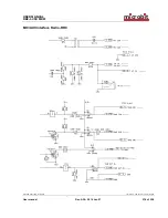
Page 215: ...ob t RRC 1258 MKII Ba1258B_RemoteRig_MkIIs A30 Microbit 2 0 AB 2010 All rights reserved a User manual Rev A30 2014 Jan 21 215 of 228 Speaker output interface Control RRC MkIIs Speaker input interface...

Page 216: ...USER MANUAL m crob t RRC 1258 MKII Ba1258B_RemoteRig_MkIIs A30 Microbit 2 0 AB 2010 All rights reserved a User manual Rev A30 2014 Jan 21 216 of 228 MIC AUX Interface Radio RRC...

Page 217: ...be configured so that port 13000 13001 13002 and 80 default settings are directed to the Radio RRC which should have a static IP address The easy way to get connected is to set the RRC IP address as...

Page 218: ...Ba1258B_RemoteRig_MkIIs A30 Microbit 2 0 AB 2010 All rights reserved a User manual Rev A30 2014 Jan 21 218 of 228 DMZ A typical setup screen for activating DMZ is shown below Enter the IP number of t...

Page 219: ...0 Microbit 2 0 AB 2010 All rights reserved a User manual Rev A30 2014 Jan 21 219 of 228 Portforwarding A typical setup screen for activating port forwarding is shown below There is one row assigned fo...

Page 220: ...II Ba1258B_RemoteRig_MkIIs A30 Microbit 2 0 AB 2010 All rights reserved a User manual Rev A30 2014 Jan 21 220 of 228 SIP ALG If the router has a parameter called SIP ALG it should always be Disabled i...

Page 221: ...y as a normal router Before you order your 3G or 4G subscription check with the operator that they allow inbound connections from outside Internet some operators do not and you need that if you will h...

Page 222: ...duced The other qualities are more of academic interest A good speaker is always a good investment also Note Different codings can be used in the uplink and downlink which can be useful in asymmetrica...

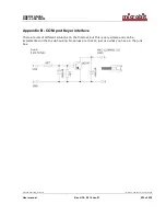
Page 223: ...All rights reserved a User manual Rev A30 2014 Jan 21 223 of 228 Appendix B COM port Keyer interface There are lots of different solutions on the Internet but this is very simple and can be implemente...

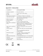
Page 224: ...amplifier 2 x 2W 8 ohm Mic input Dynamic or Electret with DC feed Radio protocol detachable front Kenwood TS 480 TM D710 TS 2000 ICOM IC 703 IC 706 IC E2820 IC R2500 IC 2725 FT 857 FT 100 FT 7800 880...

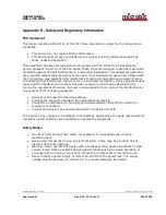
Page 225: ...ference to radio or television reception which can be determined by turning the equipment off and on the user is encouraged to try to correct the interference by one or more of the following measures...

Page 226: ...s not guarantee that the contents will satisfy the desire and expectation of the reader The author or Microbit takes no responsibility for damage or injuries of any kind that may arise from the use an...

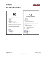
Page 227: ...USER MANUAL m crob t RRC 1258 MKII Ba1258B_RemoteRig_MkIIs A30 Microbit 2 0 AB 2010 All rights reserved a User manual Rev A30 2014 Jan 21 227 of 228 FCC CE Declaration of conformity...

Page 228: ...58B_RemoteRig_MkIIs A30 Microbit 2 0 AB 2010 All rights reserved a User manual Rev A30 2014 Jan 21 228 of 228 Appendix F Contact Information Support site www remoterig com E mail info microbit se Web...

Reviews: