USER MANUAL
m crob t
RRC-1258 MKII
Ba1258B_RemoteRig_MkIIs-A30
Microbit 2.0 AB 2010. All rights reserved
a
User manual
Rev. A30
– 2014 Jan 21
24 of 228
7:
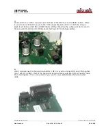
Control-RRC Only: JMP-4 is placed behind the CW-pot, and is available only in the Control-
RRC and are only present in the RRC-1258MkIIs up to Hardware version 5. JMP-4 is used to
select between Speaker level or Headset level for the Main-Rx output. The Sub-Rx is always
Headset level. From hardware version 6 it’s always speaker level from both RX.
8:
JMP-5 is placed behind the TLL connector and is only present in the RRC-1258MkIIs from
hardware version 7. JMP-5 is used to decide if pin1 in the TTL connector should be grounded
or not. It should be grounded (in place) for all Radios but Yaesu FT-857 and ICOM ID-E-880


