Installation
2021 Microchip Technology Inc.
DS50003057A-page 13
to 30 minutes. When stabilized, the alarm indicator turns off and the lock indicator
illuminates. The alarm relay is reset and all signal outputs are activated.
Note:
Applying the power to the instrument initiates the warm-up and automatic
lock acquisition sequence. During this time, the alarm relay is activated and
the signal outputs are not active.
2.7
INSTALLING THE MONITOR3 SOFTWARE
The Monitor3 software runs on any PC or laptop running Microsoft Windows 95 or
newer. It requires less than 1 MB of disk space and one available serial (COM) port to
connect to the CsIII.
Following are the steps to install the Monitor3 software:
1. Download the Monitor3 software from Microchip FTD support website.
2. Install the application by running the setup.exe file.
By default, the Monitor3 application is installed in the c:\Program Files\Symmetricom
directory. A folder named “Symmetricom” is added to your Start menu containing an
icon for the Monitor3 application. An uninstall icon is also added so that you can easily
remove the program in the future.
For DB9 connector, see the following table for connector pin-out information.
2.8
ESTABLISHING COMMUNICATIONS
Connect the serial port of the computer to the RS-232 port of the CsIII using a standard
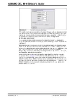
RS-232 null modem cable. Click Start, select Programs > Symmetricom > Monitor3.
The Monitor3 interface appears as shown in
The following are the default RS-232 settings of CsIII.
• BAUD = 9600
• Data bits = 7
• Parity = Odd
• Stop bits = 2
To reconfigure these settings on the CsIII, see
Appendix B. “Programmer’s Guide”
By default, Monitor3 initially attempts to connect to the instrument using the above
parameters and PC serial port COM1. To check or adjust these communication param
-
eters, select Configure Serial Port from the File menu. The panel shown in
appears. Use this panel to adjust the Monitor3 serial communications parameters to
agree with the setting of the CsIII instrument.
TABLE 2-1:
RS-233 PORT DB9 TO DB25 CONNECTOR PIN-OUT
DB9-M
DB25-F
Function
3
3
Rx Data
2
2
Tx Data
5
7
Signal GND
TABLE 2-2:
RS-232 PORT DB9 TO DB9 CONNECTOR PIN-OUT
DB9-M
DB9-F
Function
3
2
Rx Data
2
3
Tx Data
5
5
Signal GND
Summary of Contents for 4310B
Page 1: ...2021 Microchip Technology Inc Advance Information DS50003057A CSIII Model 4310B User s Guide...
Page 26: ...CSIII MODEL 4310B User s Guide DS50003057A page 26 2021 Microchip Technology Inc NOTES...
Page 38: ...CSIII Model 4310B User s Guide DS50003057A page 38 2021 Microchip Technology Inc NOTES...
Page 46: ...CSIII Model 4310B User s Guide DS50003057A page 46 2021 Microchip Technology Inc NOTES...
Page 48: ...CSIII Model 4310B User s Guide DS50003057A page 48 2021 Microchip Technology Inc NOTES...

