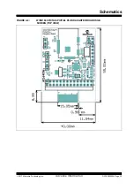
WINC1500 PICtail
TM
/PICtail Plus Daughter Board User’s Guide
DS70005309A-Page 16
Advance Information
2017 Microchip Technology Inc.
2.1.3
I
2
C Debug Header (J1)
The WINC1500 PICtail/PICtail Plus Daughter Board has an UART debug header which
connects the I
2
C debug interface to the ATWINC1510-MR210PB module. This header
is not populated.
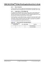
Table 2-2
provides the pinout details of the I
2
C debug header.
2.1.4
GPIO Debug Header (J4)
The WINC1500 PICtail/PICtail Plus Daughter Board has an UART debug header which
connects the GPIO debug interface to the ATWINC1510-MR210PB module. This
header is not populated.
Table 2-3
provides the pinout details of the GPIO debug
header.
2.1.5
UART Debug Header (J3)
The WINC1500 PICtail/PICtail plus daughter board has an UART debug header which
connects the UART debug interface to the ATWINC1510-MR210PB module. This
header is not populated.
Table 2-4
provides the pinout of the UART debug header.
TABLE 2-2:
I
2
C DEBUG HEADER PINOUT
Pin on I
2
C debug header
(J1)
Pin on
ATWINC1510-MR210PB
Function
1
2
ATWINC1500 SCL
2
9, 12, 28
GND
3
3
ATWINC1500 SDA
4
—
No connection
TABLE 2-3:
GPIO DEBUG HEADER PINOUT
Pin on GPIO debug
header (J4)
Pin on
ATWINC1510-MR210PB
Function
1
11
ATWINC1500 WAKE
2
21
ATWINC1500 GPIO_1
3
25
ATWINC1500 GPIO_3
4
26
ATWINC1500 GPIO_4
5
27
ATWINC1500 GPIO_5
6
1
ATWINC1500 GPIO_6
TABLE 2-4:
UART DEBUG HEADER PINOUT
Pin on I
2
C debug header
(J1)
Pin on
ATWINC1510-MR210PB
Function
1
19
ATWINC1500 UART RX
2
14
ATWINC1500 UART TX
3
9,12, 28
GND


