Product Overview
2015 Microchip Technology Inc.
DS50002379A-page 15
1.3
WHAT IS THE MCP19111 PMBus™ PROTOCOL-ENABLED POINT-OF-LOAD
CONVERTER REFERENCE DESIGN?
The MCP19111 PMBus™ Protocol-Enabled Point-of-Load Converter Reference
Design demonstrates how the MCP19111 device operates in a synchronous buck
topology over a wide input voltage and load range. Nearly all operational and control
system parameters are programmable by utilizing the integrated PIC microcontroller.
For precise measurements of the output current, a precision op amp
(MCP6061) and
an inductor temperature sensor (MCP9700) are provided. The output current may be
measured and calibrated using an internal or external op amp. The temperature
compensation may be performed by temperature measurement or by second order
polynomial approximation.
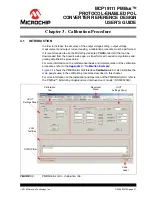
The PMBus Monitoring Graphical User Interface (GUI) can be used to program the
functioning parameters and to check the operational status. To simplify the connection,
a USB to PMBus converter is implemented on board, allowing a standard interface to
any Windows
®
computer.
Alternatively, the user can program the MCP19111 using self-developed firmware (see
Section 1.4.1 “The Development System’s Components”
), tailoring it to the
application.
The evaluation board contains headers for In-Circuit Serial Programming™ (ICSP™)
as well as I
2
C and mini-USB communication, pull-up and pull-down resistor pads and
test point pads on each GPIO pin, and a push button for system development. The
MCP19111 PMBus™ Protocol-Enabled Point-of-Load Converter Reference Design is
also intended to demonstrate an optimized Printed Circuit Board (PCB) layout that
minimizes parasitics, while increasing efficiency and power density.
Proper PCB layout is critical to achieve optimum MCP19111 operation, as well as
power train efficiency and noise minimization.
1.4
SYSTEM REQUIREMENTS
To operate the board, the following tools are required:
• Microsoft
®
.NET Framework 4.5 or higher
• PMBus Monitoring Graphical User Interface: This graphical user interface allows
monitoring and changing input and output parameters for any device that has an
incorporated PMBus™ protocol. For installation, operation and other system
requirements, see the
“PMBus™ Monitoring Graphical User Interface User’s
Guide”
(DS50002380).
WARNING
Any changes in the Settings tab from the Developer menu may result in system
instability and/or permanent damage of the board, and is the user’s sole responsibility
to take the necessary precautions.

