3.
Kit Setup
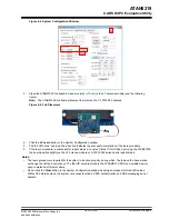
Perform the following steps to set up the ATAK51005-V1 kit:
1.
On the ATSAMC21-XPRO microcontroller board, ensure that the VCC-SEL jumper is set to the 5.0V position.
2.
If using the ATA5291-XPRO board, perform the following actions; otherwise, skip to step 3.
– Insert the ATA5291-XPRO LF coil driver/immobilizer board in the EXT3 connector on the ATSAMC21-
XPRO board.
– Connect the ATAB-LFTX LF antenna module to Ant0 on the ATA5291-XPRO board.
– Ensure that the J1 jumper on the LF antenna module is set to the inductor only (
) position, and go
to step 4.
Note:
For use of the antenna on the Ant1-7 connectors, ensure that the jumper on the LF antenna
module is set to the LCR position.
3.
If using the ATA5293-XPRO, perform the following actions:
– Insert the ATA5293-XPRO LF coil driver/immobilizer board in the EXT3 connector on the ATSAMC21-
XPRO board.
– Connect the X-10013-002 antenna to Ant0 on the ATA5293-XPRO board.
Note:
For use of the Ant1-5 and 8 connectors, the X-10013-003 antenna is required.
ATAN0219
Kit Setup
©
2020-2022 Microchip Technology Inc.
and its subsidiaries
User Guide
DS50003051B-page 8

