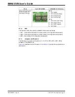
BM62 EVB User’s Guide
DS70005260C - Page 20
2016-2017 Microchip Technology Inc.
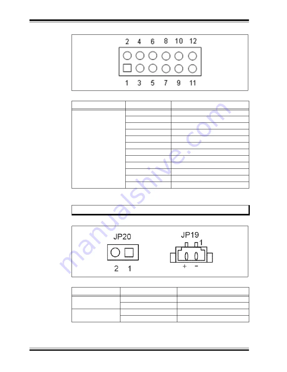
FIGURE 2-3:
EXTERNAL MCU HEADER J6
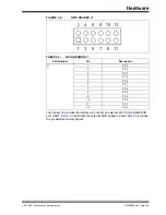
illustrates the battery connector JP20 and JP19, and
provides the
pin details and descriptions.
FIGURE 2-4:
BATTERY CONNECTOR JP20 AND JP19
TABLE 2-5:
EXTERNAL MCU HEADER J6
Part Number
Pin
Description
JP2
1
NC
2
HCI_RXD
3
NC
4
HCI_TXD
5
GND
6
GND
7
NC
8
RST_N
9
NC
10
MFB (for RX_IND)
11
NFC
12
P0_0 (for TX_IND)
Note:
The Li-Ion battery can be connected to JP20 or JP19 of the BM62 EVB.
TABLE 2-6:
BATTERY CONNECTOR JP20 AND JP19
Part Number
Pin
Description
JP20
1
BAT_IN
2
GND
JP19
1
GND
2
BAT_IN
Summary of Contents for BM62
Page 1: ...2016 2017 Microchip Technology Inc DS70005260C BM62 Evaluation Board EVB User s Guide...
Page 4: ...BM62 EVB User s Guide DS70005260C Page 4 2016 2017 Microchip Technology Inc NOTES...
Page 10: ...BM62 EVB User s Guide DS70005260C Page 10 2016 2017 Microchip Technology Inc NOTES...
Page 58: ...BM62 EVB User s Guide DS70005260C Page 58 2016 2017 Microchip Technology Inc NOTES...
Page 62: ...BM62 EVB User s Guide DS70005260C Page 62 2016 2017 Microchip Technology Inc NOTES...
Page 65: ...Schematics 2016 2017 Microchip Technology Inc DS70005260C Page 65 FIGURE B 4 NFC TAG CIRCUIT...
Page 75: ...2016 2017 Microchip Technology Inc DS70005260C Page 75 NOTES...


