Getting Started
2016-2017 Microchip Technology Inc.
DS70005260C - Page 43
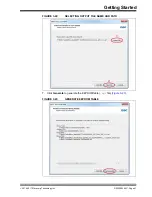
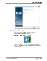
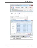
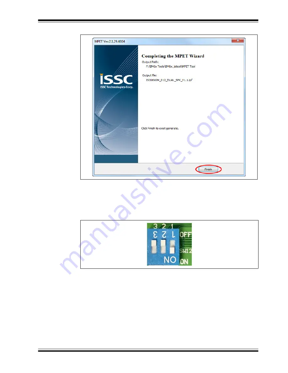
FIGURE 3-25:
GENERATED OUTPUT FILE
3.5
UPDATING EEPROM PARAMETERS
Perform the following actions to update the EEPROM parameters.
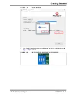
1. Set switch SW12 to Test Mode (
).
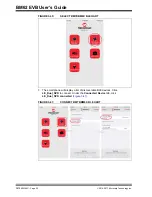
FIGURE 3-26:
SWITCH SW12 IN TEST MODE
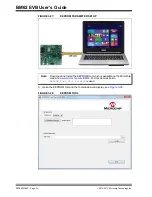
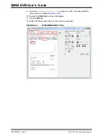
2. Connect the BM62 EVB to a PC using a micro-USB cable as illustrated in
. The default LED behavior in Test mode is: LED1 and LED2
(blue
and red) will be ON.
Summary of Contents for BM62
Page 1: ...2016 2017 Microchip Technology Inc DS70005260C BM62 Evaluation Board EVB User s Guide...
Page 4: ...BM62 EVB User s Guide DS70005260C Page 4 2016 2017 Microchip Technology Inc NOTES...
Page 10: ...BM62 EVB User s Guide DS70005260C Page 10 2016 2017 Microchip Technology Inc NOTES...
Page 58: ...BM62 EVB User s Guide DS70005260C Page 58 2016 2017 Microchip Technology Inc NOTES...
Page 62: ...BM62 EVB User s Guide DS70005260C Page 62 2016 2017 Microchip Technology Inc NOTES...
Page 65: ...Schematics 2016 2017 Microchip Technology Inc DS70005260C Page 65 FIGURE B 4 NFC TAG CIRCUIT...
Page 75: ...2016 2017 Microchip Technology Inc DS70005260C Page 75 NOTES...


