background image

 2014 Microchip Technology Inc.

DS40001746A-page 10

MCS3142 DUAL K

EE

L

OQ® 

ENCODER

WIRELESS REMOTE CONTROL

DEVELOPMENT KIT USER’S GUIDE

Chapter 2.  Quick Start

2.1

INTRODUCTION

The MCS3142 Dual K

EE

L

OQ

 Encoder Wireless Remote Control Development Kit uses 

an identical receiver module and demo board as seen in the Wireless Security Remote 
Control Development Kit User’s Guide. 
(

http://ww1.microchip.com/downloads/en/DeviceDoc/41646A.pdf

). This chapter will 

explain how to setup the board and show


the general operation.

2.2

USING THE STAND-ALONE DEMO

2.2.1

Setup

There are only a few steps to perform to get the stand-alone demo working:
1. Open the plastic enclosure of the red key fob by carefully prying apart the two 

halves with a flat-head screw driver. Observe the correct battery polarity and 
insert the coin battery into the holder. Put the key fob back together. 

2. To verify that the key fob is properly installed, press any button and the LED 

should flash when a button is pressed.

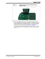
3. Plug in the RF receiver daughter board on the PICtail slot of the demo board. 

Make sure that the RF receiver daughter board has the side with the RF receiver 
chip facing the center, as shown in Figure 2-1.

Summary of Contents for DM182017-4

Page 1: ...2014 Microchip Technology Inc DS40001746A MCS3142 Dual KEELOQ Encoder Wireless Remote Control Development Kit User s Guide...

Page 2: ...e protection feature may be a violation of the Digital Millennium Copyright Act If such acts allow unauthorized access to your software or other copyrighted work you may have a right to sue for relief...

Page 3: ...DS40001746A page 3 2014 Microchip Technology Inc Object of Declaration MCS3142 Dual KEELOQ Encoder Wireless Remote Control Development Kit...

Page 4: ...9 Chapter 2 Quick Start 2 1 Introduction 10 2 2 Using the Stand alone Demo 10 2 2 1 Setup 10 2 2 2 Operation 12 2 3 KEELOQ Screens 13 Chapter 3 Hardware Self Test 3 1 Introduction 18 3 2 Button Tests...

Page 5: ...t SQTP 32 7 3 1 SQTP File Generation 32 7 3 2 File format 33 7 3 3 Generate Source 34 Chapter 8 PC Application 8 1 Introduction 35 8 1 1 PC Application Features 35 8 1 2 PC Requirements 35 8 2 Install...

Page 6: ...NT LAYOUT This document describes how to use the MCS3142 Dual KEELOQ Encoder Wireless Remote Control Development Kit as a development tool to emulate and debug firmware on a target board The manual la...

Page 7: ...enu path File Save Bold characters A dialog button Click OK A tab Click the Power tab N Rnnnn A number in verilog format where N is the total number of digits R is the radix and n is a digit 4 b0010 2...

Page 8: ...be found on www microchip com keeloq THE MICROCHIP WEB SITE Microchip provides online support via our web site at www microchip com This web site is used as a means to make files and information easi...

Page 9: ...Office Field Application Engineer FAE Technical Support Customers should contact their distributor representative or field application engineer FAE for support Local sales offices are also available t...

Page 10: ...form and MCS3142 transmitter that are used in conjunction with each other to showcase the various technologies of KEELOQ Classic KEELOQ and Ultimate KEELOQ For details on Classic KEELOQ and Ultimate K...

Page 11: ...general operation 2 2 USING THE STAND ALONE DEMO 2 2 1 Setup There are only a few steps to perform to get the stand alone demo working 1 Open the plastic enclosure of the red key fob by carefully pryi...

Page 12: ...nect a USB A to mini B cable to the development board and an available USB port Set jumper J6 to pins 1 2 No drivers are required to power the board however the MCP2200 driver may need to be installed...

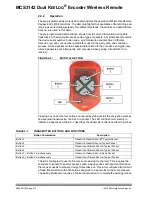
Page 13: ...Pressing any one of the four buttons on the red key fob will start the encryption process and eventual transmission of a KEELOQ packet The LED will flash momentarily to indicate a transmission Table...

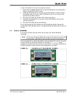
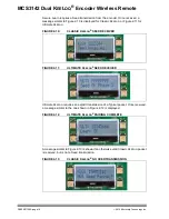
Page 14: ...kit also includes the SX1239 Receiver PICtail Daughter Board It houses the Semtech SX1239 wideband receiver The target application configured the receiver on start up 2 3 KEELOQ SCREENS This section...

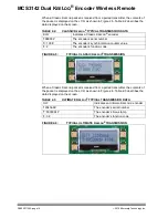
Page 15: ...ansmitter the contents of the packet is displayed on the LCD as shown in Figure 2 6 Table 2 3 describes the data displayed on the screen FIGURE 2 6 TYPICAL ULTIMATE KEELOQ TRANSMISSION TABLE 2 2 CLASS...

Page 16: ...enters Normal Learn mode text similar to Figure 2 7 is displayed For Secure Learn text similar to Figure 2 8 is shown FIGURE 2 7 ENTER NORMAL LEARN MODE FIGURE 2 8 ENTER SECURE LEARN MODE The receiver...

Page 17: ...KEELOQ FIGURE 2 10 CLASSIC KEELOQ SEED RECEIVED FIGURE 2 11 ULTIMATE KEELOQ SEED RECEIVED Ultimate KEELOQ requires an explicit transmission of a Typical packet Once received a message similar to the...

Page 18: ...N ERROR Packets from Ultimate KEELOQ encoders are always validated initially by confirming the Authorization Code portion of the transmission If this check fails a message similar to Figure 2 15 is di...

Page 19: ...pressed the test instruction message will be changed for the next push button Once all push buttons have been tested SW1 needs to be pressed to move forward to the LED test 3 3 LED TESTS There are tw...

Page 20: ...arts Once the SPI test starts the target application microcontroller requests specific information from the SX1239 receiver through the SPI bus If the expected response is received then the Successful...

Page 21: ...4 MCS3142 Wireless Remote Key Fob 4 1 INTRODUCTION The MCS3142 Wireless Remote Key Fob is a demonstration and development platform for wireless security remote control applications Please see http ww1...

Page 22: ...5 1 EMBEDDED SECURITY DEVELOPMENT BOARD The following main blocks are defined on the Embedded Security Development Board in Table 5 1 TABLE 5 1 EMBEDDED SECURITY MODULE DEFINITIONS 1 Target Applicati...

Page 23: ...l connector J1 the Serial Accessory Port P20 four push button switches SW1 SW4 and four LEDs D4 D7 The PIC16LF1938 microcontroller can be programmed debugged via the ICSP J5 The Embedded Security Deve...

Page 24: ...he Microchip web site http www microchip com for accessory daughter boards with PICtail port 5 6 LCD DISPLAY The Embedded Security Development Board supports 16x2 character LCD display with backlight...

Page 25: ...ed the RE3 MCLR pin of target application microcontroller is configured to be a normal digital I O pin therefore the MCLR push button is ineffective Otherwise if an I2C intercommunication is not requi...

Page 26: ...to program the target application microcontroller Figure 5 2 shows the ICSP ports FIGURE 5 2 ICSP HEADERS FOR BOTH MICROS 5 12 SX1239 RECEIVER PICtail DAUGHTER BOARD The SX1239 PICtail Receiver Daught...

Page 27: ...crochip Technology development tools The antenna connection has a pin socket for plugging a wire antenna This demonstrates a simple and low cost antenna option The antenna pin socket can be removed by...

Page 28: ...ailable on the key fob PCB as six contact areas The following steps need to be followed to program the MCS3142 Remove the PCB board from the plastic enclosure and lay the PCB board on a non conductive...

Page 29: ...FIGURE 6 1 BLOCK DIAGRAM DESIGN OF THE SOFTWARE ON THE TARGET CONTROLLER Encoder Mediator This file contains the place where custom code can be entered after the algorithm is done checking for a vali...

Page 30: ...on code that grab data and send to the host controller This code should be left untouched since it has no effect on the actual data manipulation of KEELOQ SX1239 This is the receiver that the target u...

Page 31: ...main project The tool uses the current main project inside of MPLAB X to select the correct device and workspace to attach the generated code The KEELOQ plugin is available from the Plugin Center of...

Page 32: ...THE MAIN PROJECT SO THAT THE PLUGIN CORRECTLY RECOGNIZES THE DEVICE Usage The plugin can be launched via Tools Embedded Keeloq FIGURE 7 3 THE PLUGIN REQUIRES A MAIN PROJECT THAT HAS A KEELOQ DEVICE SE...

Page 33: ...ereby each chip is programmed with a slightly different code Typically all locations are programmed with the same basic code except for a few contiguous bytes which are programmed with a different num...

Page 34: ...R_1 SEED_0 SEED_1 RESERVED CONFIG Taking the sample data and adding these brackets to make it more readable B0 B8 C5 3F 37 D7 B3 FF 00 00 00 00 00 00 00 00 17 7A A5 50 00 00 00 00 Please consult with...

Page 35: ...ELOQ device The Generate Source button will place a single assembly file labeled MemoryMap asm into the project s workspace under Source Files This file contains the calculated values such as the encr...

Page 36: ...Only MAC platforms that meet this requirement will be able to correctly connect to the board 8 2 INSTALLATION 8 2 1 Installing the Wireless Security Remote Kit GUI The installer can be downloaded from...

Page 37: ...releases of the program software A default Windows 7 look and feel was used for all figures Place the jumper on J6 on the Embedded Security Development Board in its left most position to enable USB po...

Page 38: ...tion between the demo board If successful the dialog box will disappear and the Main window will contain similar text as below FIGURE 8 3 DIALOG OUTPUT IMMEDIATELY FOLLOWING A SUCCESSFUL CONNECTION No...

Page 39: ...8 4 PAIRING A TRANSMITTER The demo board and PC application are now synchronized with one another Once successfully paired a text box will be populated with the learned data being sent to the PC for i...

Page 40: ...hic blocks and text boxes as the Transmit button on the learned fob is pressed The figures below show the two panels that have been updated after the previously learned device has its transmission rec...

Page 41: ...A page 40 2014 Microchip Technology Inc FIGURE 8 7 CLASSIC GRAPHIC UPDATED WITH A SINGLE TRANSMISSION BY A PREVIOUSLY LEARNED DEVICE 8 5 1 KEELOQ Graphic Specifics Each graphic contains a Pie on the r...

Page 42: ...smitter Each time a transmission is authenticated the intended function is executed and the transmission s synchroniza tion counter value is stored in EEPROM From the currently stored counter value th...

Page 43: ...ransmission will update the Receiver Clock block with the receiver s time The transmitter s time is symbolized by the black line and should land directly in between the two blue lines The blue lines r...

Page 44: ...changes to the board The kits come with a receiver that has a matching circuit that is designed to a specific frequency Changing the frequency far from its originally designed center frequency will ha...

Page 45: ...F C9 DNP R1 C2 C3 C5 1000pF C4 GND GND RFOUT RFOUT DATA DATA GND GND GND GND GND GND VCC VCC VCC 1pF C1 VCC VCC GND GND PGD_SW0 PGC_SW1 LED SW2 XTAL SOSCI SOSCO MCLR_SW3 SOSCI SOSCO Value ANT1 ANT_LOO...

Page 46: ...A U1 Microcontroller MCS3142 I SS Microchip MCS3142 I SS N A N A Enclosure Polycase FB 20 4 9 X2 32 768 kHz Crystal Abracon AB26TRB 32 768KHZ T 315 MHz C5 1 nF Capacitor Murata GRM1555C1H102JA01D C3...

Page 47: ...070RL L1 27 nH Inductor Murata LQG15HS27NJ02D X1 26 MHz Crystal Abracon ABM8G 26 000MHZ 18 D2Y T 915 MHz C5 0 W Resistor Yageo RC0402JR 070RL C3 6 8 pF Capacitor Murata GRM1555C1H6R8DA01D C1 0 5 pF C...

Page 48: ...ENCODER WIRELESS REMOTE CONTROL DEVELOPMENT KIT USER S GUIDE 2014 Microchip Technology Inc DS40001746A page 47 Appendix B SX1239 Receiver PICtail Daughter Board Schematics FIGURE B 1 SX1239 RECEIVER P...

Page 49: ...ntenna Connection SX1239IMLTRT VBAT1 1 VR_ANA 2 VR_DIG 3 NC 24 SCK 15 MOSI 17 NSS 18 RESET 6 XTA 4 XTB 5 GND 14 GND 20 GND 22 PAD 25 VBAT2 13 RFIO 21 DIO0 7 DIO1 DCLK 8 DIO2 DATA 9 DIO3 10 DIO4 11 DIO...

Page 50: ...ata GRM155R71C104KA88D A1 N A Wire 24 AWG Alpha Wire 3050 1 YL005 E1 N A Pin Receptacle Mill max 0667 0 15 01 30 27 10 0 J1 N A Terminal strip SAMTEC TSW 114 08 F D RA S1 N A Switch DPDT E Switch EG13...

Page 51: ...DER WIRELESS REMOTE CONTROL DEVELOPMENT KIT USER S GUIDE 2014 Microchip Technology Inc DS40001746A page 50 Appendix C Embedded Security Development Board Schematics FIGURE C 1 EMBEDDED SECURITY DEVELO...

Page 52: ...Embedded Security Development Board Schematics 2014 Microchip Technology Inc DS40001746A page 51 FIGURE C 2 HOST CONTROLLER OF THE EMBEDDED SECURITY DEVELOPMENT BOARD SCHEMATIC...

Page 53: ...Dual KEELOQ Encoder Wireless Remote Control Development Kit User s Guide DS40001746A page 52 2014 Microchip Technology Inc FIGURE C 3 TARGET APPLICATION OF THE EMBEDDED SECURITY DEVELOPMENT BOARD SCH...

Page 54: ...C2 0 1 F Murata GRM188R71E104KA01D C3 0 1 F Murata GRM188R71E104KA01D C4 0 1 F Murata GRM188R71E104KA01D C5 0 1 F Murata GRM188R71E104KA01D C6 0 1 F Murata GRM188R71E104KA01D C7 0 1 F Murata GRM188R71...

Page 55: ...ional RMCF0603FT100R 16 R2 330 Stackpole Electronics International RMCF0603FT330R R4 330 Stackpole Electronics International RMCF0603FT330R R5 330 Stackpole Electronics International RMCF0603FT330R R6...

Page 56: ...k Stackpole Electronics International RMCF0603FT100K 1 R3 1 M Stackpole Electronics International RMCF0603FT1M00 1 S1 E Switch EG1390B 9 SW1 Omron B3S 1000P SW2 Omron B3S 1000P SW3 Omron B3S 1000P SW4...

Page 57: ...x 86 24 2334 2393 China Shenzhen Tel 86 755 8864 2200 Fax 86 755 8203 1760 China Wuhan Tel 86 27 5980 5300 Fax 86 27 5980 5118 China Xian Tel 86 29 8833 7252 Fax 86 29 8833 7256 China Xiamen Tel 86 59...

Reviews: