2004 Microchip Technology Inc.
Advance Information
DS70119B-page 103
dsPIC30F6010
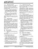
17.9
IPMI Support
The control bit IPMIEN enables the module to support
Intelligent Peripheral Management Interface (IPMI).
When this bit is set, the module accepts and acts upon
all addresses.
17.10 General Call Address Support
The general call address can address all devices.
When this address is used, all devices should, in the-
ory, respond with an acknowledgement.
The general call address is one of eight addresses
reserved for specific purposes by the I
2
C protocol. It
consists of all
0
’s with R_W =
0
.
The general call address is recognized when the Gen-
eral Call Enable (GCEN) bit is set (I2CCON<15> =
1
).
Following a start bit detection, 8 bits are shifted into
I2CRSR and the address is compared with I2CADD,
and is also compared with the general call address
which is fixed in hardware.
If a general call address match occurs, the I2CRSR is
transferred to the I2CRCV after the eighth clock, the
RBF flag is set, and on the falling edge of the ninth bit
(ACK bit), the master event interrupt flag (MI2CIF) is
set.
When the interrupt is serviced, the source for the inter-
rupt can be checked by reading the contents of the
I2CRCV to determine if the address was device
specific, or a general call address.
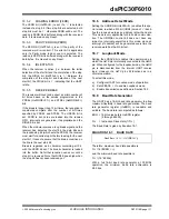
17.11 I
2
C Master Support
As a Master device, six operations are supported.
• Assert a Start condition on SDA and SCL.
• Assert a Restart condition on SDA and SCL.
• Write to the I2CTRN register initiating
transmission of data/address.
• Generate a Stop condition on SDA and SCL.
• Configure the I
2
C port to receive data.
• Generate an ACK condition at the end of a
received byte of data.
17.12 I
2
C Master Operation
The master device generates all of the serial clock
pulses and the Start and Stop conditions. A transfer is
ended with a Stop condition or with a Repeated Start
condition. Since the Repeated Start condition is also
the beginning of the next serial transfer, the I
2
C bus will
not be released.
In Master Transmitter mode, serial data is output
through SDA, while SCL outputs the serial clock. The
first byte transmitted contains the slave address of the
receiving device (7 bits) and the data direction bit. In
this case, the data direction bit (R_W) is logic
0
. Serial
data is transmitted 8 bits at a time. After each byte is
transmitted, an ACK bit is received. Start and Stop con-
ditions are output to indicate the beginning and the end
of a serial transfer.
In Master Receive mode, the first byte transmitted con-
tains the slave address of the transmitting device (7
bits) and the data direction bit. In this case, the data
direction bit (R_W) is logic
1
. Thus, the first byte trans-
mitted is a 7-bit slave address, followed by a ‘
1
’ to indi-
cate receive bit. Serial data is received via SDA, while
SCL outputs the serial clock. Serial data is received 8
bits at a time. After each byte is received, an ACK bit is
transmitted. Start and Stop conditions indicate the
beginning and end of transmission.
17.12.1
I
2
C MASTER TRANSMISSION
Transmission of a data byte, a 7-bit address, or the sec-
ond half of a 10-bit address is accomplished by simply
writing a value to I2CTRN register. The user should
only write to I2CTRN when the module is in a WAIT
state. This action will set the buffer full flag (TBF) and
allow the baud rate generator to begin counting and
start the next transmission. Each bit of address/data
will be shifted out onto the SDA pin after the falling
edge of SCL is asserted. The Transmit Status Flag,
TRSTAT (I2CSTAT<14>), indicates that a master
transmit is in progress.
17.12.2
I
2
C MASTER RECEPTION
Master mode reception is enabled by programming the
receive enable (RCEN) bit (I2CCON<11>). The I
2
C
module must be Idle before the RCEN bit is set, other-
wise the RCEN bit will be disregarded.
The baud rate
generator begins counting, and on each rollover, the
state of the SCL pin toggles, and data is shifted in to the
I2CRSR on the rising edge of each clock.
17.12.3
BAUD RATE GENERATOR
In I
2
C Master mode, the reload value for the BRG is
located in the I2CBRG register. When the BRG is
loaded with this value, the BRG counts down to 0 and
stops until another reload has taken place. If clock arbi-
tration is taking place, for instance, the BRG is reloaded
when the SCL pin is sampled high.
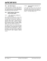
As per the I
2
C standard, FSCK may be 100 kHz or
400 kHz. However, the user can specify any baud rate
up to 1 MHz. I2CBRG values of
0
or
1
are illegal.
EQUATION 17-1: SERIAL CLOCK RATE
FSCK = F
CY
/ I2CBRG
Summary of Contents for dsPIC30F6010
Page 12: ...dsPIC30F6010 DS70119B page 10 Advance Information 2004 Microchip Technology Inc NOTES...
Page 32: ...dsPIC30F6010 DS70119B page 30 Advance Information 2004 Microchip Technology Inc NOTES...
Page 38: ...dsPIC30F6010 DS70119B page 36 Advance Information 2004 Microchip Technology Inc NOTES...
Page 50: ...dsPIC30F6010 DS70119B page 48 Advance Information 2004 Microchip Technology Inc NOTES...
Page 68: ...dsPIC30F6010 DS70119B page 66 Advance Information 2004 Microchip Technology Inc NOTES...
Page 72: ...dsPIC30F6010 DS70119B page 70 Advance Information 2004 Microchip Technology Inc NOTES...
Page 76: ...dsPIC30F6010 DS70119B page 74 Advance Information 2004 Microchip Technology Inc NOTES...
Page 86: ...dsPIC30F6010 DS70119B page 84 Advance Information 2004 Microchip Technology Inc NOTES...
Page 108: ...dsPIC30F6010 DS70119B page 106 Advance Information 2004 Microchip Technology Inc NOTES...
Page 116: ...dsPIC30F6010 DS70119B page 114 Advance Information 2004 Microchip Technology Inc NOTES...
Page 128: ...dsPIC30F6010 DS70119B page 126 Advance Information 2004 Microchip Technology Inc NOTES...
Page 150: ...dsPIC30F6010 DS70119B page 148 Advance Information 2004 Microchip Technology Inc NOTES...
Page 164: ...dsPIC30F6010 DS70119B page 162 Advance Information 2004 Microchip Technology Inc NOTES...
Page 208: ...dsPIC30F6010 DS70119B page 206 Advance Information 2004 Microchip Technology Inc NOTES...
Page 220: ...dsPIC30F6010 DS70119B page 220 Advance Information 2004 Microchip Technology Inc NOTES...
Page 221: ...2004 Microchip Technology Inc Advance Information DS70119B page 221 dsPIC30F6010 NOTES...

