background image

dsPIC30F6010

DS70119B-page 128

Advance Information

 2004 Microchip Technology Inc.

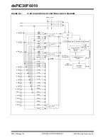
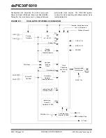
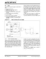
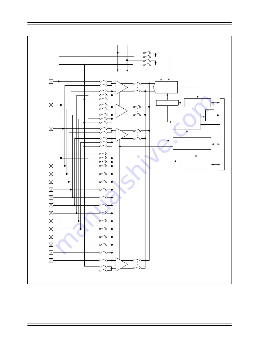
FIGURE 20-1:

10-BIT HIGH SPEED A/D FUNCTIONAL BLOCK DIAGRAM

S/H

+

-

10-bit Result

Conversion Logic

V

REF

+

AV

SS

AV

DD

ADC

Dat

a

16-word, 10-bit

Dual Port

Buffer

Bus Interface

AN12

AN0

AN5

AN7

AN9

AN13

AN14

AN15

AN12

AN1
AN2
AN3

AN4

AN6

AN8

AN10

AN11

AN13

AN14

AN15

AN8

AN9

AN10

AN11

AN4

AN5

AN6

AN7

AN0

AN1

AN2

AN3

CH1

CH2

CH3

CH0

AN5

AN2

AN11

AN8

AN4

AN1

AN10

AN7

AN3

AN0

AN9

AN6

AN1

V

REF

-

Sample/Sequence

Control

sample

CH1,CH2,
CH3,CH0

Input Mux

Control

input

switches

S/H

+

-

S/H

+

-

S/H

+

-

Format

Summary of Contents for dsPIC30F6010

Page 1: ...2004 Microchip Technology Inc Advance Information DS70119B dsPIC30F6010 Data Sheet High Performance Digital Signal Controllers...

Page 2: ...ective companies 2004 Microchip Technology Incorporated Printed in the U S A All Rights Reserved Printed on recycled paper Note the following details of the code protection feature on Microchip device...

Page 3: ...DSP instructions single cycle 16 bit single cycle shift Peripheral Features High current sink source I O pins 25 mA 25 mA Timer module with programmable prescaler Five 16 bit timers counters optionall...

Page 4: ...it Serial Programming ICSP Selectable Power Management modes Sleep Idle and Alternate Clock modes CMOS Technology Low power high speed Flash technology Wide operating voltage range 2 5V to 5 5V Indust...

Page 5: ...RA15 IC3 RD10 INT3 RA14 VSS OSC1 CLKI VDD SCL RG2 U1RX RF2 U1TX RF3 EMUC1 SOSCO T1CK CN0 RC14 EMUD1 SOSCI CN1 RC13 V REF RA10 V REF RA9 AV DD AV SS AN8 RB8 AN9 RB9 AN10 RB10 AN11 RB11 V DD U2RX CN17...

Page 6: ...questions or comments regarding this publication please contact the Marketing Communications Department via E mail at docerrors mail microchip com or fax the Reader Response Form in the back of this...

Page 7: ...W This document contains device specific information for the dsPIC30F6010 device The dsPIC30F devices contain extensive Digital Signal Processor DSP func tionality within a high performance 16 bit mic...

Page 8: ...N10 RG8 SS2 CN11 RG9 U2TX CN18 RF5 EMUC3 SCK1 INT0 RF6 SDI1 RF7 EMUD3 SDO1 RF8 Input Capture Module Output Compare Module EMUC1 SOSCO T1CK CN0 RC14 EMUD1 SOSCI CN1 RC13 T4CK RC3 T2CK RC1 PORTB C1RX RF...

Page 9: ...in Data Converter Interface serial data output pin C1RX C1TX C2RX C2TX I O I O ST ST CAN1 bus receive pin CAN1 bus transmit pin CAN2 bus receive pin CAN2 bus transmit pin EMUD EMUC EMUD1 EMUC1 EMUD2 E...

Page 10: ...RA14 RA15 I O I O ST ST PORTA is a bi directional I O port RB0 RB15 I O ST PORTB is a bi directional I O port RC1 RC3 RC13 RC15 I O I O I O ST ST ST PORTC is a bi directional I O port RD0 RD15 I O ST...

Page 11: ...UART1 Receive UART1 Transmit UART1 Alternate Receive UART1 Alternate Transmit UART2 Receive UART2 Transmit VDD P Positive supply for logic and I O pins VSS P Ground reference for logic and I O pins VR...

Page 12: ...dsPIC30F6010 DS70119B page 10 Advance Information 2004 Microchip Technology Inc NOTES...

Page 13: ...ts of an instruction word Overhead free circular buffers modulo addressing are supported in both X and Y address spaces This is pri marily intended to remove the loop overhead for DSP algorithms The X...

Page 14: ...ce accesses 2 2 1 SOFTWARE STACK POINTER FRAME POINTER The dsPIC devices contain a software stack W15 is the dedicated software stack pointer SP and will be automatically modified by exception process...

Page 15: ...fset W13 DSP Write Back W14 Frame Pointer W15 Stack Pointer DSP Address Registers AD39 AD0 AD31 DSP Accumulators AccA AccB PSVPAG 7 0 Program Space Visibility Page Address Z 0 OA OB SA SB RCOUNT 15 0...

Page 16: ...ogic The dsPIC30F devices have a single instruction flow which can execute either DSP or MCU instructions Many of the hardware resources are shared between the DSP and MCU instructions For example the...

Page 17: ...P ENGINE BLOCK DIAGRAM Zero Backfill Sign Extend Barrel Shifter 40 bit Accumulator A 40 bit Accumulator B Round Logic X Data Bus To From W Array Adder Saturate Negate 32 32 33 16 16 16 16 40 40 40 40...

Page 18: ...on source and post accumulation destina tion For the ADD and LAC instructions the data to be accumulated or loaded can be optionally scaled via the barrel shifter prior to accumulation 2 4 2 1 Adder S...

Page 19: ...rflow can initiate a trap exception 2 4 2 2 Accumulator Write Back The MAC class of instructions with the exception of MPY MPY N ED and EDAC can optionally write a rounded version of the high word bit...

Page 20: ...mory is forced to the maximum negative 1 15 value 0x8000 The MS bit of the source bit 39 is used to determine the sign of the operand being tested If the SATDW bit in the CORCON register is not set th...

Page 21: ...r all accesses other than TBLRD TBLWT which use TBLPAG 7 to determine user or configura tion space access In Table 3 1 Read Write instruc tions bit 23 allows access to the Device ID the User ID and th...

Page 22: ...RD TBLWT User TBLPAG 7 0 TBLPAG 7 0 Data EA 15 0 TBLRD TBLWT Configuration TBLPAG 7 1 TBLPAG 7 0 Data EA 15 0 Program Space Visibility User 0 PSVPAG 7 0 Data EA 14 0 0 Program Counter 23 bits 1 PSVPAG...

Page 23: ...TBLWTL access the space which contains the LS Data Word and TBLRDH and TBLWTH access the space which contains the MS Data Byte Figure 3 2 shows how the EA is created for table oper ations and data sp...

Page 24: ...ammed to force an illegal instruction to maintain machine robustness Refer to the dsPIC30F Programmer s Reference Manual DS70030 for details on instruction encoding Note that by incrementing the PC by...

Page 25: ...sists of the 64 Kbyte data address space excluding the Y address block for data reads only In other words all other instructions regard the entire data memory as one composite address space The MAC cl...

Page 26: ...7FE 0x17FE 0xFFFE LS Byte Address 16 bits LSB MSB MS Byte Address 0x0001 0x07FF 0x17FF 0xFFFF 0x8001 0x8000 Optionally Mapped into Program Memory 0x27FF 0x27FE 0x2800 0x2801 0x0801 0x0800 0x1801 0x180...

Page 27: ...7 DATA SPACE FOR MCU AND DSP MAC CLASS INSTRUCTIONS EXAMPLE SFR SPACE Y SPACE X SPACE SFR SPACE UNUSED X SPACE X SPACE Y SPACE UNUSED UNUSED Non MAC Class Ops Read Write MAC Class Ops Read Only Indir...

Page 28: ...64 Kbytes or 32K words 3 2 3 DATA SPACE WIDTH The core data width is 16 bits All internal registers are organized as 16 bit wide words Data space memory is organized in byte addressable 16 bit wide bl...

Page 29: ...s for stack pushes as shown in Figure 3 9 Note that for a PC push during any CALL instruction the MSB of the PC is zero extended before the push ensuring that the MSB is always clear There is a Stack...

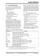
Page 30: ...IM 0020 SPLIM 0000 0000 0000 0000 ACCAL 0022 ACCAL 0000 0000 0000 0000 ACCAH 0024 ACCAH 0000 0000 0000 0000 ACCAU 0026 Sign Extension ACCA 39 ACCAU 0000 0000 0000 0000 ACCBL 0028 ACCBL 0000 0000 0000...

Page 31: ...RT 004C YS 15 1 0 uuuu uuuu uuuu uuu0 YMODEND 004E YE 15 1 1 uuuu uuuu uuuu uuu1 XBREV 0050 BREN XB 14 0 uuuu uuuu uuuu uuuu DISICNT 0052 DISICNT 13 0 0000 0000 0000 0000 TABLE 3 3 CORE REGISTER MAP C...

Page 32: ...dsPIC30F6010 DS70119B page 30 Advance Information 2004 Microchip Technology Inc NOTES...

Page 33: ...writes the result to a register or register pair The MOV instruction allows additional flexibility and can access the entire data space during file register operation 4 1 2 MCU INSTRUCTIONS The three...

Page 34: ...specify the branch destination directly whereas the DISI instruction uses a 14 bit unsigned literal field In some instructions such as ADD Acc the source of an operand or result is implied by the opc...

Page 35: ...ssing is disabled The X Address Space Pointer W register XWM to which modulo addressing is to be applied is stored in MODCON 3 0 see Table 3 3 Modulo addressing is enabled for X data space when XWM is...

Page 36: ...direct with pre increment or post increment addressing and word sized data writes It will not function for any other addressing mode or for byte sized data and normal addresses will be gener ated inst...

Page 37: ...1 0 2 0 1 0 0 4 0 0 1 1 3 1 1 0 0 12 0 1 0 0 4 0 0 1 0 2 0 1 0 1 5 1 0 1 0 10 0 1 1 0 6 0 1 1 0 6 0 1 1 1 7 1 1 1 0 14 1 0 0 0 8 0 0 0 1 1 1 0 0 1 9 1 0 0 1 9 1 0 1 0 10 0 1 0 1 5 1 0 1 1 11 1 1 0 1...

Page 38: ...dsPIC30F6010 DS70119B page 36 Advance Information 2004 Microchip Technology Inc NOTES...

Page 39: ...r table All interrupt sources can be user assigned to one of 7 priority levels 1 through 7 via the IPCx registers Each interrupt source is associated with an interrupt vector as shown in Table 5 1 Lev...

Page 40: ...R TABLE Note The user selectable priority levels start at 0 as the lowest priority and level 7 as the highest priority Note 1 The natural order priority scheme has 0 as the highest priority and 53 as...

Page 41: ...neous operation during debug and when operating within the application Note that many of these trap conditions can only be detected when they occur Consequently the question able instruction is allowe...

Page 42: ...nding in order to completely correct the fault Soft traps include exceptions of priority level 8 through level 11 inclusive The arithmetic error trap level 11 falls into this category of traps Hard tr...

Page 43: ...he AIVT is not required the program memory allo cated to the AIVT may be used for other purposes AIVT is not a protected section and may be freely programmed by the user 5 6 Fast Context Saving A cont...

Page 44: ...0 0000 0000 0000 IEC1 008E IC6IE IC5IE IC4IE IC3IE C1IE SPI2IE U2TXIE U2RXIE INT2IE T5IE T4IE OC4IE OC3IE IC8IE IC7IE INT1IE 0000 0000 0000 0000 IEC2 0090 FLTBIE FLTAIE LVDIE QEIIE PWMIE C2IE INT4IE I...

Page 45: ...Programming RTSP RTSP is accomplished using TBLRD table read and TBLWT table write instructions With RTSP the user may erase program memory 32 instructions 96 bytes at a time and can write program me...

Page 46: ...cycles because only the table latches are written After the latches are written a programming operation needs to be initiated to program the data The Flash Program Memory is readable writable and era...

Page 47: ...te 32 instruction words of data from data RAM image into the program Flash write latches 5 Program 32 instruction words into program Flash a Setup NVMCON register for multi word program Flash program...

Page 48: ...TBLPAG Initialize PM Page Boundary SFR MOV 0x6000 W0 An example program memory address Perform the TBLWT instructions to write the latches 0th_program_word MOV LOW_WORD_0 W2 MOV HIGH_BYTE_0 W3 TBLWTL...

Page 49: ...15 Bit 14 Bit 13 Bit 12 Bit 11 Bit 10 Bit 9 Bit 8 Bit 7 Bit 6 Bit 5 Bit 4 Bit 3 Bit 2 Bit 1 Bit 0 All RESETS NVMCON 0760 WR WREN WRERR TWRI PROGOP 6 0 0000 0000 0000 0000 NVMADR 0762 NVMADR 15 0 uuuu...

Page 50: ...dsPIC30F6010 DS70119B page 48 Advance Information 2004 Microchip Technology Inc NOTES...

Page 51: ...respon sible for waiting for the appropriate duration of time before initiating another data EEPROM write erase operation Attempting to read the data EEPROM while a programming or erase operation is...

Page 52: ...M block ERASE WREN bits MOV 4045 W0 MOV W0 NVMCON Initialize NVMCON SFR Start erase cycle by setting WR after writing key sequence DISI 5 Block all interrupts with priority 7 for next 5 instructions M...

Page 53: ...d code exe cution The WREN bit should be kept clear at all times except when updating the EEPROM The WREN bit is not cleared by hardware After a write sequence has been initiated clearing the WREN bit...

Page 54: ...r MOV HIGH_ADDR_WORD W1 MOV W1 TBLPAG MOV data1 W2 Get 1st data TBLWTL W2 W0 write data MOV data2 W2 Get 2nd data TBLWTL W2 W0 write data MOV data3 W2 Get 3rd data TBLWTL W2 W0 write data MOV data4 W2...

Page 55: ...t means the corresponding LATx and TRISx registers and the port pin will read as zeros When a pin is shared with another peripheral or func tion that is defined as an input only it is nevertheless reg...

Page 56: ...reading the PORT register all pins configured as analog input channel will read as cleared a low level Pins configured as digital inputs will not convert an ana log input Analog levels on any pin that...

Page 57: ...1 0000 0000 0000 0000 TRISD 02D2 TRISD15 TRISD14 TRISD13 TRISD12 TRISD11 TRISD10 TRISD9 TRISD8 TRISD7 TRISD6 TRISD5 TRISD4 TRISD3 TRISD2 TRISD1 TRISD0 1111 1111 1111 1111 PORTD 02D4 RD15 RD14 RD13 RD1...

Page 58: ...STER MAP BITS 15 8 TABLE 8 3 INPUT CHANGE NOTIFICATION REGISTER MAP BITS 7 0 SFR Name Addr Bit 15 Bit 14 Bit 13 Bit 12 Bit 11 Bit 10 Bit 9 Bit 8 Reset State CNEN1 00C0 CN15IE CN14IE CN13IE CN12IE CN11...

Page 59: ...When the CPU goes into the Idle mode the timer will stop incrementing unless the TSIDL T1CON 13 bit 0 If TSIDL 1 the timer module logic will resume the incrementing sequence upon termination of the C...

Page 60: ...T1CON 2 is asserted to a logic 0 which defines the external clock source as asynchronous When all three conditions are true the timer will con tinue to count up to the period register and be reset to...

Page 61: ...Sleep mode the RTC will con tinue to operate provided the 32 kHz external crystal oscillator is active and the control bits have not been changed The TSIDL bit should be cleared to 0 in order for RTC...

Page 62: ...ame Addr Bit 15 Bit 14 Bit 13 Bit 12 Bit 11 Bit 10 Bit 9 Bit 8 Bit 7 Bit 6 Bit 5 Bit 4 Bit 3 Bit 2 Bit 1 Bit 0 Reset State TMR1 0100 Timer 1 Register uuuu uuuu uuuu uuuu PR1 0102 Period Register 1 111...

Page 63: ...The only functional difference between Timer2 and Timer3 is that Timer2 provides synchronization of the clock prescaler output This is useful for high frequency external clock inputs 32 bit Timer Mod...

Page 64: ...Reset LSB MSB Event Flag Note Timer Configuration bit T32 T2CON 3 must be set to 1 for a 32 bit timer counter operation All control bits are respective to the T2CON register Data Bus 15 0 TMR3HLD Read...

Page 65: ...3 BLOCK DIAGRAM TYPE C TIMER TON Sync PR2 T2IF Equal Comparator x 16 TMR2 Reset Event Flag Q Q D CK TGATE TCKPS 1 0 Prescaler 1 8 64 256 2 TGATE TCY 1 0 TCS 1 X 0 1 TGATE 0 0 Gate T2CK Sync TON PR3 T3...

Page 66: ...ts TCKPS 1 0 T2CON 5 4 and T3CON 5 4 For the 32 bit timer operation the originating clock source is Timer2 The prescaler oper ation for Timer3 is not applicable in this mode The prescaler counter is c...

Page 67: ...te TMR2 0106 Timer2 Register uuuu uuuu uuuu uuuu TMR3HLD 0108 Timer3 Holding Register For 32 bit timer operations only uuuu uuuu uuuu uuuu TMR3 010A Timer3 Register uuuu uuuu uuuu uuuu PR2 010C Period...

Page 68: ...dsPIC30F6010 DS70119B page 66 Advance Information 2004 Microchip Technology Inc NOTES...

Page 69: ...For 32 bit timer counter operation Timer4 is the LS Word and Timer5 is the MS Word of the 32 bit timer FIGURE 11 1 32 BIT TIMER4 5 BLOCK DIAGRAM Note Timer4 is a Type B timer and Timer5 is a Type C t...

Page 70: ...BLOCK DIAGRAM TYPE C TIMER TON Sync PR4 T4IF Equal Comparator x 16 TMR4 Reset Event Flag Q Q D CK TGATE TCKPS 1 0 Prescaler 1 8 64 256 2 TGATE TCY 1 0 TCS 1 X 0 1 TGATE 0 0 Gate T4CK Sync TON PR5 T5I...

Page 71: ...ate TMR4 0114 Timer 4 Register uuuu uuuu uuuu uuuu TMR5HLD 0116 Timer 5 Holding Register For 32 bit operations only uuuu uuuu uuuu uuuu TMR5 0118 Timer 5 Register uuuu uuuu uuuu uuuu PR4 011A Period R...

Page 72: ...dsPIC30F6010 DS70119B page 70 Advance Information 2004 Microchip Technology Inc NOTES...

Page 73: ...g edge Capture every rising and falling edge These simple Input Capture modes are configured by setting the appropriate bits ICM 2 0 ICxCON 2 0 12 1 1 CAPTURE PRESCALER There are four input capture pr...

Page 74: ...Interrupt Enable bit is asserted The same wake up can generate an interrupt if the conditions for processing the interrupt have been satisfied The wake up feature is useful as a method of adding extr...

Page 75: ...uuu uuuu IC3CON 014A ICSIDL ICTMR ICI 1 0 ICOV ICBNE ICM 2 0 0000 0000 0000 0000 IC4BUF 014C Input 4 Capture Register uuuu uuuu uuuu uuuu IC4CON 014E ICSIDL ICTMR ICI 1 0 ICOV ICBNE ICM 2 0 0000 0000...

Page 76: ...dsPIC30F6010 DS70119B page 74 Advance Information 2004 Microchip Technology Inc NOTES...

Page 77: ...t Compare during Sleep and Idle modes Interrupt on Output Compare PWM Event These operating modes are determined by setting the appropriate bits in the 16 bit OCxCON SFR where x 1 2 3 N The dsPIC30F60...

Page 78: ...iate another single pulse issue another write to set OCM 2 0 100 13 3 2 CONTINUOUS PULSE MODE For the user to configure the module for the generation of a continuous stream of output pulses the follow...

Page 79: ...device wakes up 13 6 Output Compare Operation During CPU Idle Mode When the CPU enters the Idle mode the output compare module can operate with full functionality The output compare channel will opera...

Page 80: ...0 0000 0000 0000 0000 OC4RS 0192 Output Compare 4 Secondary Register 0000 0000 0000 0000 OC4R 0194 Output Compare 4 Main Register 0000 0000 0000 0000 OC4CON 0196 OCSIDL OCFLT OCTSEL OCM 2 0 0000 0000...

Page 81: ...se filters on inputs Alternate 16 bit Timer Counter mode Quadrature Encoder Interface interrupts These operating modes are determined by setting the appropriate bits QEIM 2 0 QEICON 10 8 Figure 14 1 d...

Page 82: ...I 2 controls whether the position counter is reset when the index pulse is detected This bit is only applicable when QEIM 2 0 100 or 110 If the POSRES bit is set to 1 then the position counter is rese...

Page 83: ...ernal Up Down input select When the UPDN pin is asserted high the timer will increment up When the UPDN pin is asserted low the timer will be decremented The UPDN Control Status bit QEICON 11 can be u...

Page 84: ...the CPU Idle mode had not been entered 14 8 Quadrature Encoder Interface Interrupts The quadrature encoder interface has the ability to generate an interrupt on occurrence of the following events Inte...

Page 85: ...6 Bit 5 Bit 4 Bit 3 Bit 2 Bit 1 Bit 0 Reset State QEICON 0122 CNTERR QEISIDL INDX UPDN QEIM2 QEIM1 QEIM0 SWPAB PCDOUT TQGATE TQCKPS1 TQCKPS0 POSRES TQCS UPDN_SRC 0000 0000 0000 0000 DFLTCON 0124 IMV1...

Page 86: ...dsPIC30F6010 DS70119B page 84 Advance Information 2004 Microchip Technology Inc NOTES...

Page 87: ...Aligned Output modes Single Pulse Generation mode Interrupt support for asymmetrical updates in Center Aligned mode Output override control for Electrically Commutative Motor ECM operation Special Ev...

Page 88: ...Manual Control SFR Channel 3 Dead Time Generator and Channel 2 Dead Time Generator and PWM Generator 3 PWM Generator 2 PWM Generator 4 SEVTDIR PTDIR DTCON1 Dead Time Control SFRs Special Event Postsca...

Page 89: ...nt upwards as long as the PTEN bit remains set When the PWM time base is in the Free Running mode PTMOD 1 0 00 an interrupt event is generated each time a match with the PTPER register occurs and the...

Page 90: ...o the PTPER register at the following instants Free Running and Single Shot modes When the PTMR register is reset to zero after a match with the PTPER register Up Down Counting modes When the PTMR reg...

Page 91: ...holds the actual compare value used in the present PWM period For edge aligned PWM output a new duty cycle value will be updated whenever a match with the PTPER reg ister occurs and PTMR is reset The...

Page 92: ...GNMENT The DTCON2 SFR contains control bits that allow the dead times to be assigned to each of the complemen tary outputs Table 15 1 summarizes the function of each dead time selection control bit TA...

Page 93: ...th the PTPER register occurs the PTMR reg ister is cleared all active PWM I O pins are driven to the inactive state the PTEN bit is cleared and an interrupt is generated 15 10 PWM Output Override The...

Page 94: ...idden by a FAULT input When these bits are cleared the PWM I O pin is driven to the inactive state If the bit is set the PWM I O pin will be driven to the active state The active and inactive states a...

Page 95: ...e SEVTCMP register When the PWM time base is in an Up Down Counting mode an additional control bit is required to specify the counting phase for the special event trigger The count phase is selected u...

Page 96: ...OPS 3 0 OSYNC UDIS 0000 0000 0000 0000 DTCON1 01CC DTBPS 1 0 Dead Time B Value DTAPS 1 0 Dead Time A Value 0000 0000 0000 0000 DTCON2 01CE DTS4A DTS4I DTS3A DTS3I DTS2A DTS2I DTS1A DTS1I 0000 0000 000...

Page 97: ...ster mode the clock is generated by prescaling the system clock Data is transmitted as soon as a value is written to SPIxBUF The interrupt is generated at the middle of the transfer of the last bit In...

Page 98: ...x SPIxSR SPIxBUF bit0 Shift clock Edge Select FCY Primary 1 4 16 64 Enable Master Clock Prescaler Secondary Prescaler 1 2 4 6 8 SS FSYNC Control Clock Control Transmit SPIxBUF Receive Serial Input Buf...

Page 99: ...at the MS bit even if SSx had been de asserted in the middle of a transmit receive 16 4 SPI Operation During CPU Sleep Mode During Sleep mode the SPI module is shut down If the CPU enters Sleep mode...

Page 100: ...MODE16 SMP CKE SSEN CKP MSTEN SPRE2 SPRE1 SPRE0 PPRE1 PPRE0 0000 0000 0000 0000 SPI1BUF 0224 Transmit and Receive Buffer 0000 0000 0000 0000 Legend u uninitialized bit SFR Name Addr Bit 15 Bit 14 Bit...

Page 101: ...ation with 7 or 10 bit address See the I2 C programmer s model in Figure 17 1 FIGURE 17 1 PROGRAMMER S MODEL 17 1 2 PIN CONFIGURATION IN I2C MODE I2C has a 2 pin interface pin SCL is clock and pin SDA...

Page 102: ...Data Bus SCL SDA Shift Match Detect I2CADD Start and Stop bit Detect Clock Addr_Match Clock Stretching I2CTRN LSB Shift Clock Write Read BRG Down I2CBRG Reload Control FCY Start Restart Stop bit Gene...

Page 103: ...nsferred to I2CRCV ACK is sent on the ninth clock If the RBF flag is set indicating that I2CRCV is still holding data from a previous operation RBF 1 then ACK is not sent however the interrupt pulse i...

Page 104: ...g takes place automatically during the addressing sequence Because this module has a register for the entire address it is not necessary for the protocol to wait for the address to be updated After th...

Page 105: ...the receiving device 7 bits and the data direction bit In this case the data direction bit R_W is logic 0 Serial data is transmitted 8 bits at a time After each byte is transmitted an ACK bit is recei...

Page 106: ...P bit is set the user can resume communication by asserting a Start condition If a Start Restart Stop or Acknowledge condition was in progress when the bus collision occurred the condi tion is aborted...

Page 107: ...2CRCV 0200 Receive Register 0000 0000 0000 0000 I2CTRN 0202 Transmit Register 0000 0000 1111 1111 I2CBRG 0204 Baud Rate Generator 0000 0000 0000 0000 I2CCON 0206 I2CEN I2CSIDL SCLREL IPMIEN A10M DISSL...

Page 108: ...dsPIC30F6010 DS70119B page 106 Advance Information 2004 Microchip Technology Inc NOTES...

Page 109: ...e from 38 bps to 1 875 Mbps at a 30 MHz instruction rate 4 word deep transmit data buffer 4 word deep receive data buffer Parity Framing and Buffer Overrun error detection Support for Interrupt only o...

Page 110: ...E Receive Buffer Control Generate Flags Generate Interrupt UxRXIF UxRX Start bit Detect Receive Shift Register 16 Divider Control Signals UxSTA Shift Data Characters Read Read Write Write to Buffer 8...

Page 111: ...no parity or 9 bits with no parity The STSEL bit determines whether one or two stop bits will be used during data transmission The default Power on setting of the UART is 8 bits no parity 1 stop bit...

Page 112: ...reading UxRXREG will move the next word to the top of the receive FIFO and the PERR and FERR values will be updated 18 4 2 RECEIVE BUFFER UXRXB The receive buffer is 4 words deep Including the Receive...

Page 113: ...ume that the break condition on the line is the next start bit Break is regarded as a character containing all 0 s with the FERR bit set The break character is loaded into the buffer No further recept...

Page 114: ...ogic 1 Similarly if entry into Sleep mode occurs while a reception is in progress then the reception is aborted The UxSTA UxMODE transmit and receive registers and buffers and the UxBRG register are n...

Page 115: ...t Register 0000 000u uuuu uuuu U1RXREG 0212 URX8 Receive Register 0000 0000 0000 0000 U1BRG 0214 Baud Rate Generator Prescaler 0000 0000 0000 0000 Legend u uninitialized bit SFR Name Addr Bit 15 Bit 1...

Page 116: ...dsPIC30F6010 DS70119B page 114 Advance Information 2004 Microchip Technology Inc NOTES...

Page 117: ...le mode The CAN bus module consists of a protocol engine and message buffering control The CAN protocol engine handles all functions for receiving and transmit ting messages on the CAN bus Messages ar...

Page 118: ...Acceptance Filter RXF0 Acceptance Filter RXF1 R X B 0 MSGREQ TXB2 TXABT TXLARB TXERR MTXBUFF MESSAGE Message Queue Control Transmit Byte Sequencer MSGREQ TXB1 TXABT TXLARB TXERR MTXBUFF MESSAGE MSGRE...

Page 119: ...at condition as an idle bus then accept the module disable command When the OPMODE 2 0 bits CiCTRL 7 5 001 that indi cates whether the module successfully went into mod ule disable mode The I O pins w...

Page 120: ...is set to a zero then that bit will automatically be accepted regardless of the filter bit There are 2 programmable acceptance filter masks associated with the receive buffers one for each buffer 19...

Page 121: ...if the priority was changed it is resolved correctly before the SOF occurs When TXREQ is set the TXABT CiTXnCON 6 TXLARB CiTXnCON 5 and TXERR CiTXnCON 4 flag bits are automatically cleared Setting TX...

Page 122: ...nter has exceeded 255 and the module has gone to Bus Off state 19 6 Baud Rate Setting All nodes on any particular CAN bus must have the same nominal bit rate In order to set the baud rate the followin...

Page 123: ...e at the sample point The level determined by the CAN bus then corre sponds to the result from the majority decision of three values The majority samples are taken at the sample point and twice before...

Page 124: ...Receive Acceptance Filter 5 Extended Identifier 17 6 0000 uuuu uuuu uuuu C1RXF5EIDL 032C Receive Acceptance Filter 5 Extended Identifier 5 0 uuuu uu00 0000 0000 C1RXM0SID 0330 Receive Acceptance Mask...

Page 125: ...uuuu uuuu uuuu C1RX1B2 0378 Receive Buffer 1 Byte 3 Receive Buffer 1 Byte 2 uuuu uuuu uuuu uuuu C1RX1B3 037A Receive Buffer 1 Byte 5 Receive Buffer 1 Byte 4 uuuu uuuu uuuu uuuu C1RX1B4 037C Receive B...

Page 126: ...uu C2RXF5EIDL 03EC Receive Acceptance Filter 5 Extended Identifier 5 0 uuuu uu00 0000 0000 C2RXM0SID 03F0 Receive Acceptance Mask 0 Standard Identifier 10 0 MIDE 000u uuuu uuuu uu0u C2RXM0EIDH 03F2 Re...

Page 127: ...Byte 2 uuuu uuuu uuuu uuuu C2RX1B3 043A Receive Buffer 1 Byte 5 Receive Buffer 1 Byte 4 uuuu uuuu uuuu uuuu C2RX1B4 043C Receive Buffer 1 Byte 7 Receive Buffer 1 Byte 6 uuuu uuuu uuuu uuuu C2RX1CON 04...

Page 128: ...dsPIC30F6010 DS70119B page 126 Advance Information 2004 Microchip Technology Inc NOTES...

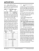
Page 129: ...r the voltage level on the VREF VREF pin The A D converter has a unique feature of being able to operate while the device is in Sleep mode The A D module has six 16 bit registers A D Control Register1...

Page 130: ...AVSS AVDD ADC Data 16 word 10 bit Dual Port Buffer Bus Interface AN12 AN0 AN5 AN7 AN9 AN13 AN14 AN15 AN12 AN1 AN2 AN3 AN4 AN6 AN8 AN10 AN11 AN13 AN14 AN15 AN8 AN9 AN10 AN11 AN4 AN5 AN6 AN7 AN0 AN1 AN...

Page 131: ...nverted The result is stored in the buffer If CHPS selects 2 channels the CH0 and CH1 channels will be sampled and converted If CHPS selects 4 channels the CH0 CH1 CH2 and CH3 channels will be sampled...

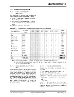
Page 132: ...the next sample pulse which corresponds with the next channel converted If simultaneous sampling is specified the A D will continue with the next multi channel group conversion sequence 20 6 Selecting...

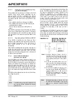
Page 133: ...tput must be captured to within 1 2 LSb error 2096 steps for 10 bit A D The CHOLD is 4 4 pF for the A D converter EQUATION 20 2 A D SAMPLING TIME EQUATIONS FIGURE 20 2 ANALOG INPUT MODEL VO VI 1 e TC...

Page 134: ...and the result loaded into the ADCBUF register If the A D interrupt is enabled the device will wake up from Sleep If the A D interrupt is not enabled the A D module will then be turned off although t...

Page 135: ...ut Analog levels on any pin that is defined as a digital input including the ANx pins may cause the input buffer to consume current that exceeds the device specifications 20 13 Connection Consideratio...

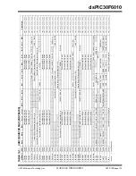
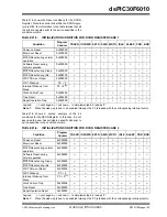
Page 136: ...uuu uuuu ADCBUFA 0294 ADC Data Buffer 10 0000 00uu uuuu uuuu ADCBUFB 0296 ADC Data Buffer 11 0000 00uu uuuu uuuu ADCBUFC 0298 ADC Data Buffer 12 0000 00uu uuuu uuuu ADCBUFD 029A ADC Data Buffer 13 000...

Page 137: ...n saves power 21 1 Oscillator System Overview The dsPIC30F oscillator system has the following modules and features Various external and internal oscillator options as clock sources An on chip PLL to...

Page 138: ...YSTEM BLOCK DIAGRAM Primary OSC1 OSC2 SOSCO SOSCI Oscillator 32 kHz LP Clock and Control Block Switching Oscillator x4 x8 x16 PLL Primary Oscillator Stability Detector Stability Detector Secondary Osc...

Page 139: ...ATOR CONTROL Enabling the LP oscillator is controlled with two elements 1 The current oscillator group bits COSC 1 0 2 The LPOSCEN bit OSCON register The LP oscillator is ON even during Sleep mode if...

Page 140: ...on Reset because it is the clock source for the PWRT After the PWRT expires the LPRC oscillator will remain ON if one of the following is TRUE The Fail Safe Clock Monitor is enabled The WDT is enabled...

Page 141: ...t values FOS 1 0 LOCK The LOCK status bit indicates a PLL lock CF Read only status bit indicating if a clock fail detect has occurred OSWEN Control bit changes from a 0 to a 1 when a clock transition...

Page 142: ...MCLR pin low FIGURE 21 2 RESET SYSTEM BLOCK DIAGRAM 21 3 1 POR POWER ON RESET A power on event will generate an internal POR pulse when a VDD rise is detected The Reset pulse will occur at the POR cir...

Page 143: ...TIME OUT SEQUENCE ON POWER UP MCLR NOT TIED TO VDD CASE 1 FIGURE 21 5 TIME OUT SEQUENCE ON POWER UP MCLR NOT TIED TO VDD CASE 2 TPWRT TOST VDD INTERNAL POR PWRT TIME OUT OST TIME OUT INTERNAL Reset MC...

Page 144: ...ines or voltage sags due to exces sive current draw when a large inductive load is turned on The BOR module allows selection of one of the follow ing voltage trip points 2 0V 2 7V 4 2V 4 5V A BOR will...

Page 145: ...0x000000 0 0 0 0 1 0 0 0 0 WDT Wake up PC 2 0 0 0 0 1 0 1 0 0 Interrupt Wake up from Sleep PC 2 1 0 0 0 0 0 0 1 0 0 Clock Failure Trap 0x000004 0 0 0 0 0 0 0 0 0 Trap Reset 0x000000 1 0 0 0 0 0 0 0 0...

Page 146: ...VDEN bit RCON 12 21 6 Power Saving Modes There are two power saving states that can be entered through the execution of a special instruction PWRSAV These are Sleep and Idle The format of the PWRSAV i...

Page 147: ...atus bits are both set Unlike wake up from Sleep there are no time delays involved in wake up from Idle 21 7 Device Configuration Registers The configuration bits in each device configuration reg iste...

Page 148: ...line and the EMUC pin is the Emulation Debug Clock line These pins will interface to the MPLAB ICD 2 module available from Microchip The selected pair of Debug I O pins is used by MPLAB ICD 2 to send...

Page 149: ...NOSC 1 0 POST 1 0 LOCK CF LPOSCEN OSWEN Depends on configuration bits PMD1 0770 T5MD T4MD T3MD T2MD T1MD QEIMD PWMMD I2CMD U2MD U1MD SPI2MD SPI1MD C2MD C1MD ADCMD 0000 0000 0000 0000 PMD2 0772 IC8MD...

Page 150: ...dsPIC30F6010 DS70119B page 148 Advance Information 2004 Microchip Technology Inc NOTES...

Page 151: ...ithout an address modi fier or file register specified by the value of Ws or f The bit in the W register or file register specified by a literal value or indirectly by the contents of register Wb The...

Page 152: ...IN OPCODE DESCRIPTIONS Field Description text Means literal defined by text text Means content of text text Means the location addressed by text Optional field or operation n m Register bit field b By...

Page 153: ...ion working registers W0 W15 Wns One of 16 source working registers W0 W15 WREG W0 working register used in file register instructions Ws Source W register Ws Ws Ws Ws Ws Ws Wso Source W register Wns...

Page 154: ...N Z 5 BCLR BCLR f bit4 Bit Clear f 1 1 None BCLR Ws bit4 Bit Clear Ws 1 1 None 6 BRA BRA C Expr Branch if Carry 1 1 2 None BRA GE Expr Branch if greater than or equal 1 1 2 None BRA GEU Expr Branch if...

Page 155: ...Ws 1 1 N Z 18 CP CP f Compare f with WREG 1 1 C DC N OV Z CP Wb lit5 Compare Wb with lit5 1 1 C DC N OV Z CP Wb Ws Compare Wb with Ws Wb Ws 1 1 C DC N OV Z 19 CP0 CP0 f Compare f with 0x0000 1 1 C DC...

Page 156: ...R lit10 Wn Wd lit10 IOR Wd 1 1 N Z IOR Wb Ws Wd Wd Wb IOR Ws 1 1 N Z IOR Wb lit5 Wd Wd Wb IOR lit5 1 1 N Z 43 LAC LAC Wso Slit4 Acc Load Accumulator 1 1 OA OB OAB SA SB SAB 44 LNK LNK lit14 Link frame...

Page 157: ...mode 1 1 WDTO Sleep 58 RCALL RCALL Expr Relative Call 1 2 None RCALL Wn Computed Call 1 2 None 59 REPEAT REPEAT lit14 Repeat Next Instruction lit14 1 times 1 1 None REPEAT Wn Repeat Next Instruction W...

Page 158: ...it5 Wd Wd Wb lit5 C 1 1 C DC N OV Z 75 SUBR SUBR f f WREG f 1 1 C DC N OV Z SUBR f WREG WREG WREG f 1 1 C DC N OV Z SUBR Wb Ws Wd Wd Ws Wb 1 1 C DC N OV Z SUBR Wb lit5 Wd Wd lit5 Wb 1 1 C DC N OV Z 76...

Page 159: ...based application that contains An interface to debugging tools simulator programmer sold separately emulator sold separately in circuit debugger sold separately A full featured editor with color code...

Page 160: ...c memory allocation data conversion time keeping and math functions trigonometric exponential and hyperbolic The compiler provides symbolic information for high level source debugging with the MPLAB I...

Page 161: ...ent tools The PC platform and Microsoft Windows 32 bit operating system were chosen to best make these features available in a simple unified application 23 11 MPLAB ICD 2 In Circuit Debugger Microchi...

Page 162: ...17 PICDEM 2 Plus Demonstration Board The PICDEM 2 Plus demonstration board supports many 18 28 and 40 pin microcontrollers including PIC16F87X and PIC18FXX2 devices All the neces sary hardware and so...

Page 163: ...ide LIN bus communication 23 23 PICkit 1 Flash Starter Kit A complete development system in a box the PICkit Flash Starter Kit includes a convenient multi section board for programming evaluation and...

Page 164: ...dsPIC30F6010 DS70119B page 162 Advance Information 2004 Microchip Technology Inc NOTES...

Page 165: ...e 2 1 0W Maximum current out of VSS pin 300 mA Maximum current into VDD pin 250 mA Input clamp current IIK VI 0 or VI VDD 20 mA Output clamp current IOK VO 0 or VO VDD 20 mA Maximum output current sun...

Page 166: ...ure 40 C TA 85 C for Industrial 40 C TA 125 C for Extended Param No Symbol Characteristic Min Typ 1 Max Units Conditions Operating Voltage 2 DC10 VDD Supply Voltage 2 5 5 5 V Industrial temperature DC...

Page 167: ...C22c mA 125 C DC22d mA 40 C 5V DC22e mA 25 C DC22f mA 85 C DC22g mA 125 C DC23 mA 40 C 3 V 4 MIPS EC mode 4X PLL DC23a 13 mA 25 C DC23b mA 85 C DC23c mA 125 C DC23d mA 40 C 5V DC23e 22 mA 25 C DC23f m...

Page 168: ...ED DC CHARACTERISTICS Standard Operating Conditions 2 5V to 5 5V unless otherwise stated Operating temperature 40 C TA 85 C for Industrial 40 C TA 125 C for Extended Parameter No Typical 1 Max Units C...

Page 169: ...ng Conditions 2 5V to 5 5V unless otherwise stated Operating temperature 40 C TA 85 C for Industrial 40 C TA 125 C for Extended Parameter No Typical 1 Max Units Conditions Operating Current IDD 2 Note...

Page 170: ...DC40e 5 mA 25 C DC40f mA 85 C DC40g mA 125 C DC41 mA 40 C 3V 2 5 MIPS EC mode DC41a 4 8 mA 25 C DC41b mA 85 C DC41c mA 125 C DC41d mA 40 C 5V DC41e 8 6 mA 25 C DC41f mA 85 C DC41g mA 125 C DC42 mA 40...

Page 171: ...C DC46f mA 85 C DC46g mA 125 C DC47 mA 40 C 3V 20 MIPS EC mode 8X PLL DC47a 29 mA 25 C DC47b mA 85 C DC47c mA 40 C 5V DC47d 52 mA 25 C DC47e mA 85 C DC47f mA 125 C TABLE 24 4 DC CHARACTERISTICS IDLE...

Page 172: ...LPRC 512 kHz DC51a 1 0 mA 25 C DC51b mA 85 C DC51c mA 125 C DC51d mA 40 C 5 V DC51e 1 5 mA 25 C DC51f mA 85 C DC51g mA 125 C TABLE 24 4 DC CHARACTERISTICS IDLE CURRENT IIDLE CONTINUED DC CHARACTERIST...

Page 173: ...b A 85 C DC61c A 125 C DC61d A 40 C 5V DC61e 16 A 25 C DC61f A 85 C DC61g A 125 C DC62 A 40 C 3V Timer 1 w 32 kHz Crystal ITI32 3 DC62a 5 5 A 25 C DC62b A 85 C DC62c A 125 C DC62d A 40 C 5V DC62e 7 5...

Page 174: ...DC CHARACTERISTICS POWER DOWN CURRENT IPD CONTINUED DC CHARACTERISTICS Standard Operating Conditions 2 5V to 5 5V unless otherwise stated Operating temperature 40 C TA 85 C for Industrial 40 C TA 125...

Page 175: ...9 VDD VDD V DI28 SDA SCL TBD TBD V SM bus disabled DI29 SDA SCL TBD TBD V SM bus enabled ICNPU CNXX Pull up Current 2 DI30 50 250 400 A VDD 5V VPIN VSS DI31 TBD TBD TBD A VDD 3V VPIN VSS IIL Input Le...

Page 176: ...KOUT 0 6 V IOL 1 6 mA VDD 5V RC or EC Osc mode TBD V IOL 2 0 mA VDD 3V VOH Output High Voltage 2 DO20 I O ports VDD 0 7 V IOH 3 0 mA VDD 5V TBD V IOH 2 0 mA VDD 3V DO26 OSC2 CLKOUT VDD 0 7 V IOH 1 3 m...

Page 177: ...on VDD transition high to low LVDL 0000 2 V LVDL 0001 2 V LVDL 0010 2 V LVDL 0011 2 V LVDL 0100 2 50 2 65 V LVDL 0101 2 70 2 86 V LVDL 0110 2 80 2 97 V LVDL 0111 3 00 3 18 V LVDL 1000 3 30 3 50 V LVD...

Page 178: ...erature 40 C TA 85 C for Industrial 40 C TA 125 C for Extended Param No Symbol Characteristic Min Typ 1 Max Units Conditions Data EEPROM Memory 2 D120 ED Byte Endurance 100K 1M E W 40 C TA 85 C D121 V...

Page 179: ...CE TIMING SPECIFICATIONS FIGURE 24 4 EXTERNAL CLOCK TIMING AC CHARACTERISTICS Standard Operating Conditions 2 5V to 5 5V unless otherwise stated Operating temperature 40 C TA 85 C for Industrial 40 C...

Page 180: ...P osc HS osc OS31 TosR TosF External Clock 2 in OSC1 Rise or Fall Time TBD TBD TBD TBD ns ns ns ns XTL osc XT osc LP osc HS osc OS40 TckR CLKOUT Rise Time 2 4 6 10 ns OS41 TckF CLKOUT Fall Time 2 4 6...

Page 181: ...ec 2 MIPS 3 w o PLL MIPS 3 w PLL x4 MIPS 3 w PLL x8 MIPS 3 w PLL x16 EC 0 200 20 0 0 05 4 1 0 1 0 4 0 8 0 16 0 10 0 4 2 5 10 0 20 0 25 0 16 25 0 XT 4 1 0 1 0 4 0 8 0 16 0 10 0 4 2 5 10 0 20 0 Note 1 A...

Page 182: ...Conditions DO31 TIOR Port output rise time 10 25 ns DO32 TIOF Port output fall time 10 25 ns DI35 TINP INTx pin high or low time output 20 ns DI40 TRBP CNx high or low time input 2 TCY ns Note 1 These...

Page 183: ...E 24 6 RESET WATCHDOG TIMER OSCILLATOR START UP TIMER AND POWER UP TIMER TIMING CHARACTERISTICS VDD MCLR Internal POR PWRT Time out OSC Time out Internal RESET Watchdog Timer RESET SY11 SY10 SY20 SY13...

Page 184: ...5V 40 C to 85 C TWDT2 1 9 2 1 2 3 ms VDD 3V 40 C to 85 C SY25 TBOR Brown out Reset Pulse Width 3 100 s VDD VBOR D034 SY30 TOST Oscillation Start up Timer Period 1024 TOSC TOSC OSC1 period SY35 TFSCM...

Page 185: ...ns Must also meet parameter TA15 Synchronous with prescaler 10 ns Asynchronous 10 ns TA10 TTXL TxCK Low Time Synchronous no prescaler 0 5 TCY 20 ns Must also meet parameter TA15 Synchronous with pres...

Page 186: ...ut Period Synchronous no prescaler TCY 10 ns N prescale value 1 8 64 256 Synchronous with prescaler Greater of 20 ns or TCY 40 N TB20 TCKEXTMRL Delay from External TQCK Clock Edge to Timer Increment 2...

Page 187: ...dustrial 40 C TA 125 C for Extended Param No Symbol Characteristic 1 Min Typ Max Units Conditions TQ11 TtQH TQCK High Time Synchronous with prescaler TCY 20 ns Must also meet parameter TQ15 TQ10 TtQL...

Page 188: ...scaler 0 5 TCY 20 ns With Prescaler 10 ns IC15 TccP ICx Input Period 2 TCY 40 N ns N prescale value 1 4 16 Note 1 These parameters are characterized but not tested in manufacturing AC CHARACTERISTICS...

Page 189: ...e 40 C TA 85 C for Industrial 40 C TA 125 C for Extended Param No Symbol Characteristic 1 Min Typ 2 Max Units Conditions OC15 TFD Fault Input to PWM I O Change 25 ns VDD 3V 40 C to 85 C TBD ns VDD 5V...

Page 190: ...onditions MP10 TFPWM PWM Output Fall Time 10 25 ns VDD 5V 40 C to 85 C MP11 TRPWM PWM Output Rise Time 10 25 ns VDD 5V 40 C to 85 C MP12 TFPWM PWM Output Fall Time TBD TBD ns VDD 3V 40 C to 85 C MP13...

Page 191: ...TQ31 TQUH Quadrature Input High Time 6 TCY ns TQ35 TQUIN Quadrature Input Period 12 TCY ns TQ36 TQUP Quadrature Phase Period 3 TCY ns TQ40 TQUFL Filter Time to Recognize Low with Digital Filter 3 N TC...

Page 192: ...with Digital Filter 3 N TCY ns N 1 2 4 16 32 64 128 and 256 Note 2 TQ51 TqiH Filter Time to Recognize High with Digital Filter 3 N TCY ns N 1 2 4 16 32 64 128 and 256 Note 2 TQ55 Tqidxr Index Pulse Re...

Page 193: ...ta Output Fall Time 4 10 25 ns SP31 TdoR SDOX Data Output Rise Time 4 10 25 ns SP35 TscH2doV TscL2doV SDOX Data Output Valid after SCKX Edge 30 ns SP40 TdiV2scH TdiV2scL Setup Time of SDIX Data Input...

Page 194: ...1 TdoR SDOX data output rise time 4 10 25 ns SP35 TscH2doV TscL2doV SDOX data output valid after SCKX edge 30 ns SP36 TdoV2sc TdoV2scL SDOX data output setup to first SCKX edge 30 ns SP40 TdiV2scH Tdi...

Page 195: ...t Fall Time 3 10 25 ns SP31 TdoR SDOX Data Output Rise Time 3 10 25 ns SP35 TscH2doV TscL2doV SDOX Data Output Valid after SCKX Edge 30 ns SP40 TdiV2scH TdiV2scL Setup Time of SDIX Data Input to SCKX...

Page 196: ...strial 40 C TA 125 C for Extended Param No Symbol Characteristic 1 Min Typ 2 Max Units Conditions Note 1 These parameters are characterized but not tested in manufacturing 2 Data in Typ column is at 5...

Page 197: ...ime 3 10 25 ns SP35 TscH2doV TscL2doV SDOX Data Output Valid after SCKX Edge 30 ns SP40 TdiV2scH TdiV2scL Setup Time of SDIX Data Input to SCKX Edge 20 ns SP41 TscH2diL TscL2diL Hold Time of SDIX Data...

Page 198: ...NG CHARACTERISTICS MASTER MODE FIGURE 24 22 I2 C BUS DATA TIMING CHARACTERISTICS MASTER MODE IM31 IM34 SCL SDA Start Condition Stop Condition IM30 IM33 Note Refer to Figure 24 3 for load conditions IM...

Page 199: ...THD DAT Data Input Hold Time 100 kHz mode 0 ns 400 kHz mode 0 0 9 ms 1 MHz mode 2 TBD ns IM30 TSU STA Start Condition Setup Time 100 kHz mode TCY 2 BRG 1 ms Only relevant for repeated Start condition...

Page 200: ...y Inc FIGURE 24 23 I2 C BUS START STOP BITS TIMING CHARACTERISTICS SLAVE MODE FIGURE 24 24 I2C BUS DATA TIMING CHARACTERISTICS SLAVE MODE IS31 IS34 SCL SDA Start Condition Stop Condition IS30 IS33 IS3...

Page 201: ...ed to be from 10 to 400 pF 400 kHz mode 20 0 1 CB 300 ns 1 MHz mode 1 300 ns IS25 TSU DAT Data Input Setup Time 100 kHz mode 250 ns 400 kHz mode 100 ns 1 MHz mode 1 100 ns IS26 THD DAT Data Input Hold...

Page 202: ...r Industrial 40 C TA 125 C for Extended Param No Symbol Characteristic 1 Min Typ 2 Max Units Conditions CA10 TioF Port Output Fall Time 10 25 ns CA11 TioR Port Output Rise Time 10 25 ns CA20 Tcwf Puls...

Page 203: ...12 Leakage Current 0 001 0 244 A VINL AVSS VREFL 0V AVDD VREFH 5V Source Impedance 10 kW AD13 Leakage Current 0 001 0 244 A VINL AVSS VREFL 0V AVDD VREFH 3V Source Impedance 10 kW AD15 RSS Switch Resi...

Page 204: ...D dB AD32 SFDR Spurious Free Dynamic Range TBD dB AD33 FNYQ Input Signal Bandwidth 250 kHz AD34 ENOB Effective Number of Bits TBD TBD bits TABLE 24 36 10 BIT HIGH SPEED A D MODULE SPECIFICATIONS CONTI...

Page 205: ...schrg ch1_samp AD60 DONE ADIF ADRES 0 ADRES 1 1 2 3 4 5 6 9 5 6 8 1 Software sets ADCON SAMP to start sampling 2 Sampling starts after discharge period 3 Software clears ADCON SAMP to start conversion...

Page 206: ...ADRES 1 1 2 3 4 5 6 4 5 6 8 1 Software sets ADCON ADON to start AD operation 2 Sampling starts after discharge period 3 Convert bit 9 4 Convert bit 8 5 Convert bit 0 AD50 ch0_samp ch1_dischrg eoc 7 3...

Page 207: ...ote 1 VDD 2 7V Note 1 AD51 tRC A D Internal RC Oscillator Period 700 900 1100 ns Conversion Rate AD55 tCONV Conversion Time 13 TAD ns AD56 FCNV Throughput Rate 500 100 ksps ksps VDD VREF 5V VDD VREF 2...

Page 208: ...dsPIC30F6010 DS70119B page 206 Advance Information 2004 Microchip Technology Inc NOTES...

Page 209: ...In the event the full Microchip part number cannot be marked on one line it will be carried over to the next line thus limiting the number of available characters for customer specific information Sta...

Page 210: ...p B D1 D n 1 2 c L A A1 A2 Units INCHES MILLIMETERS Dimension Limits MIN NOM MAX MIN NOM MAX Number of Pins n 80 80 Pitch p 026 0 65 Overall Height A 047 1 20 Molded Package Thickness A2 037 039 041...

Page 211: ...4 Example 34 Implementation 34 Modifier Values table 35 Sequence Table 16 Entry 35 Block Diagrams 10 bit High Speed A D Functional 128 16 bit Timer1 Module 57 16 bit Timer4 68 16 bit Timer5 68 32 bit...

Page 212: ...GS 145 FOSC 145 FWDT 145 Device Overview 5 Divide Support 14 DSP Engine 14 Multiplier 16 dsPIC30F6010 Port Register Map 55 Dual Output Compare Match Mode 76 Continuous Pulse Mode 76 Single Pulse Mode...

Page 213: ...xample 33 Start and End Address 33 W Address Register Selection 33 Motor Control PWM Module 85 Fault Timing Characteristics 188 Timing Characteristics 188 Timing Requirements 188 MPLAB ASM30 Assembler...

Page 214: ...ode 81 Register Map 83 Timer Operation During CPU Idle Mode 82 Timer Operation During CPU Sleep Mode 81 Quadrature Decoder Timing Requirements 189 Quadrature Encoder Interface QEI Module 79 Quadrature...

Page 215: ...Edge Aligned PWM 88 PWM Output 77 Time out Sequence on Power up MCLR Not Tied to VDD Case 1 141 Time out Sequence on Power up MCLR Not Tied to VDD Case 2 141 Time out Sequence on Power up MCLR Tied to...

Page 216: ...nsmit Buffer UxTXB 109 UART1 Register Map 113 UART2 Register Map 113 Unit ID Locations 135 Universal Asynchronous Receiver Transmitter Module UART 107 W Wake up from Sleep 135 Wake up from Sleep and I...

Page 217: ...Application Notes User s Guides Articles and Sample Programs A vari ety of Microchip specific business information is also available including listings of Microchip sales offices distributors and fact...

Page 218: ...lications Manager RE Reader Response Total Pages Sent ________ From Name Company Address City State ZIP Country Telephone _______ _________ _________ Application optional Would you like a reply Y N De...

Page 219: ...PF 30 MIPS Industrial temp TQFP package Rev A Trademark Architecture Flash E Extended High Temp 40 C to 125 C I Industrial 40 C to 85 C Temperature Device ID Package PF TQFP 14x14 S Die Waffle Pack W...

Page 220: ...dsPIC30F6010 DS70119B page 220 Advance Information 2004 Microchip Technology Inc NOTES...

Page 221: ...2004 Microchip Technology Inc Advance Information DS70119B page 221 dsPIC30F6010 NOTES...


Page 222: ...hai 200051 Tel 86 21 6275 5700 Fax 86 21 6275 5060 China Shenzhen Rm 1812 18 F Building A United Plaza No 5022 Binhe Road Futian District Shenzhen 518033 China Tel 86 755 82901380 Fax 86 755 8295 1393...

Reviews: