2004 Microchip Technology Inc.
Advance Information
DS70119B-page 135
dsPIC30F6010
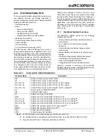
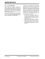
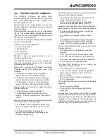
21.0 SYSTEM INTEGRATION
There are several features intended to maximize sys-
tem reliability, minimize cost through elimination of
external components, provide Power Saving Operating
modes and offer code protection:
• Oscillator Selection
• Reset
- Power-on Reset (POR)
- Power-up Timer (PWRT)
- Oscillator Start-up Timer (OST)
- Programmable Brown-out Reset (BOR)
• Watchdog Timer (WDT)
• Power Saving modes (Sleep and Idle)
• Code Protection
• Unit ID Locations
• In-Circuit Serial Programming (ICSP)
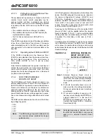
dsPIC30F devices have a Watchdog Timer, which is
permanently enabled via the configuration bits, or can
be software controlled. It runs off its own RC oscillator
for added reliability. There are two timers that offer nec-
essary delays on power-up. One is the Oscillator Start-
up Timer (OST), intended to keep the chip in Reset until
the crystal oscillator is stable. The other is the Power-
up Timer (PWRT), which provides a delay on power-up
only, designed to keep the part in Reset while the
power supply stabilizes. With these two timers on-chip,
most applications need no external Reset circuitry.
Sleep mode is designed to offer a very low current
Power-down mode. The user can wake-up from Sleep
through external Reset, Watchdog Timer Wake-up or
through an interrupt. Several oscillator options are also
made available to allow the part to fit a wide variety of
applications. In the Idle mode, the clock sources are
still active, but the CPU is shut-off. The RC oscillator
option saves system cost, while the LP crystal option
saves power.
21.1
Oscillator System Overview
The dsPIC30F oscillator system has the following
modules and features:
• Various external and internal oscillator options as
clock sources
• An on-chip PLL to boost internal operating
frequency
• A clock switching mechanism between various
clock sources
• Programmable clock postscaler for system power
savings
• A Fail-Safe Clock Monitor (FSCM) that detects
clock failure and takes fail-safe measures
• Clock Control Register OSCCON
• Configuration bits for main oscillator selection
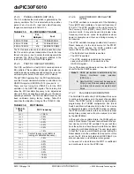
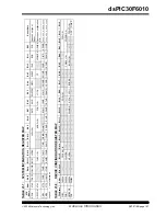
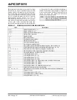
Table 21-1 provides a summary of the dsPIC30F
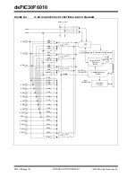
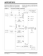
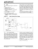
Oscillator Operating modes. A simplified diagram of the
oscillator system is shown in Figure 21-1.
TABLE 21-1:
OSCILLATOR OPERATING MODES
Oscillator Mode
Description
XTL
200 kHz-4 MHz crystal on OSC1:OSC2.
XT
4 MHz-10 MHz crystal on OSC1:OSC2.
XT w/ PLL 4x
4 MHz-10 MHz crystal on OSC1:OSC2. 4x PLL enabled.
XT w/ PLL 8x
4 MHz-10 MHz crystal on OSC1:OSC2. 8x PLL enabled.
XT w/ PLL 16x
4 MHz-10 MHz crystal on OSC1:OSC2. 16x PLL enabled
(1)
.
LP
32 kHz crystal on SOSCO:SOSCI
(2)
.
HS
10 MHz-25 MHz crystal.
EC
External clock input (0-40 MHz).
ECIO
External clock input (0-40 MHz). OSC2 pin is I/O.
EC w/ PLL 4x
External clock input (0-40 MHz). OSC2 pin is I/O. 4x PLL enabled
(1)
.
EC w/ PLL 8x
External clock input (0-40 MHz). OSC2 pin is I/O. 8x PLL enabled
(1)
.
EC w/ PLL 16x
External clock input (0-40 MHz). OSC2 pin is I/O. 16x PLL enabled
(1)
.
ERC
External RC oscillator. OSC2 pin is F
OSC
/4 output
(3)
.
ERCIO
External RC oscillator. OSC2 pin is I/O
(3)
.
FRC
8 MHz internal RC Oscillator.
LPRC
512 kHz internal RC Oscillator.
Note 1:
dsPIC30F maximum operating frequency of 120 MHz must be met.
2:
LP oscillator can be conveniently shared as system clock, as well as real-time clock for Timer1.
3:
Requires external R and C. Frequency operation up to 4 MHz.
Summary of Contents for dsPIC30F6010
Page 12: ...dsPIC30F6010 DS70119B page 10 Advance Information 2004 Microchip Technology Inc NOTES...
Page 32: ...dsPIC30F6010 DS70119B page 30 Advance Information 2004 Microchip Technology Inc NOTES...
Page 38: ...dsPIC30F6010 DS70119B page 36 Advance Information 2004 Microchip Technology Inc NOTES...
Page 50: ...dsPIC30F6010 DS70119B page 48 Advance Information 2004 Microchip Technology Inc NOTES...
Page 68: ...dsPIC30F6010 DS70119B page 66 Advance Information 2004 Microchip Technology Inc NOTES...
Page 72: ...dsPIC30F6010 DS70119B page 70 Advance Information 2004 Microchip Technology Inc NOTES...
Page 76: ...dsPIC30F6010 DS70119B page 74 Advance Information 2004 Microchip Technology Inc NOTES...
Page 86: ...dsPIC30F6010 DS70119B page 84 Advance Information 2004 Microchip Technology Inc NOTES...
Page 108: ...dsPIC30F6010 DS70119B page 106 Advance Information 2004 Microchip Technology Inc NOTES...
Page 116: ...dsPIC30F6010 DS70119B page 114 Advance Information 2004 Microchip Technology Inc NOTES...
Page 128: ...dsPIC30F6010 DS70119B page 126 Advance Information 2004 Microchip Technology Inc NOTES...
Page 150: ...dsPIC30F6010 DS70119B page 148 Advance Information 2004 Microchip Technology Inc NOTES...
Page 164: ...dsPIC30F6010 DS70119B page 162 Advance Information 2004 Microchip Technology Inc NOTES...
Page 208: ...dsPIC30F6010 DS70119B page 206 Advance Information 2004 Microchip Technology Inc NOTES...
Page 220: ...dsPIC30F6010 DS70119B page 220 Advance Information 2004 Microchip Technology Inc NOTES...
Page 221: ...2004 Microchip Technology Inc Advance Information DS70119B page 221 dsPIC30F6010 NOTES...

