2004 Microchip Technology Inc.
Advance Information
DS70119B-page 213
dsPIC30F6010
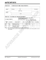
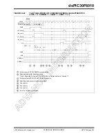
Bus Start/Stop Bits Timing Characteristics
Master Mode ..................................................... 196
Slave Mode ....................................................... 198
General Call Address Support .................................. 103
Interrupts................................................................... 102
IPMI Support ............................................................. 103
Master Operation ...................................................... 103
Master Support ......................................................... 103
Operating Function Description .................................. 99
Operation During CPU Sleep and Idle Modes .......... 104
Pin Configuration ........................................................ 99
Programmer’s Model................................................... 99
Register Map............................................................. 105
Registers..................................................................... 99
Slope Control ............................................................ 102
Software Controlled Clock Stretching (STREN = 1).. 102
Various Modes ............................................................ 99
Idle Current (I
) ............................................................ 168
In-Circuit Serial Programming (ICSP) ............................... 135
Independent PWM Output .................................................. 91
Initialization Condition for RCON Register Case 1 ........... 143
Initialization Condition for RCON Register Case 2 ........... 143
Input Capture (CAPX) Timing Characteristics .................. 186
Input Capture Interrupts ...................................................... 72
Register Map............................................................... 73
Input Capture Module ......................................................... 71
In CPU Sleep Mode .................................................... 72
Simple Capture Event Mode ....................................... 71
Input Capture Timing Requirements ................................. 186
Input Change Notification Module ....................................... 56
Input Characteristics
QEA/QEB.................................................................. 189
Instruction Addressing Modes............................................. 31
File Register Instructions ............................................ 31
Fundamental Modes Supported.................................. 31
MAC Instructions......................................................... 32
MCU Instructions ........................................................ 31
Move and Accumulator Instructions............................ 32
Other Instructions........................................................ 32
Instruction Set Overview ................................................... 152
Instruction Set Summary................................................... 149
Internal Clock Timing Examples ....................................... 179
Interrupt Controller
Register Map............................................................... 42
Interrupt Priority
Traps........................................................................... 39
Interrupt Sequence ............................................................. 41
Interrupt Stack Frame ................................................. 41
Interrupts ............................................................................. 37
L
Load Conditions ................................................................ 177
Low-Voltage Detect Characteristics .................................. 174
LVDL Characteristics ........................................................ 175
M
Memory Organization.......................................................... 19
Modulo Addressing ............................................................. 32
Applicability ................................................................. 34
Operation Example ..................................................... 33
Start and End Address................................................ 33
W Address Register Selection .................................... 33
Motor Control PWM Module ............................................... 85
MPLAB ASM30 Assembler, Linker, Librarian ................... 158
MPLAB ICD 2 In-Circuit Debugger ................................... 159
MPLAB ICE 2000 High-Performance Universal
In-Circuit Emulator.................................................... 159
MPLAB ICE 4000 High-Performance Universal
In-Circuit Emulator.................................................... 159
MPLAB Integrated Development Environment Software.. 157
MPLAB PM3 Device Programmer .................................... 159
MPLINK Object Linker/MPLIB Object Librarian ................ 158
O
OC/PWM Module Timing Characteristics ......................... 187
Operating Current (I
) .................................................... 165
Operating Frequency vs Voltage
dsPIC30FXXXX-20 (Extended) ................................ 164
Oscillator Configurations................................................... 137
Fail-Safe Clock Monitor ............................................ 138
Fast RC (FRC).......................................................... 138
Initial Clock Source Selection ................................... 137
Low Power RC (LPRC)............................................. 138
LP Oscillator Control................................................. 137
Phase Locked Loop (PLL) ........................................ 138
Start-up Timer (OST)................................................ 137
Oscillator Operating Modes Table .................................... 135
Oscillator Selection ........................................................... 135
Oscillator Start-up Timer
Timing Characteristics .............................................. 181
Timing Requirements ............................................... 182
Output Compare Interrupts ................................................. 77
Output Compare Mode
Register Map .............................................................. 78
Output Compare Module .................................................... 75
P
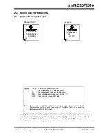
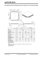
Packaging Information ...................................................... 207
Marking..................................................................... 207
PICkit 1 Flash Starter Kit .................................................. 161
PICSTART Plus Development Programmer..................... 160
Pinout Descriptions............................................................... 7
PLL Clock Timing Specifications ...................................... 179
POR.
Power-on Reset
Position Measurement Mode .............................................. 80
Power Saving Modes........................................................ 144
Idle............................................................................ 145
Sleep ........................................................................ 144
Power Saving Modes (Sleep and Idle) ............................. 135
Power-Down Current (I
PD
)................................................ 171
Power-on Reset (POR)..................................................... 135
Power-up Timer
Timing Characteristics .............................................. 181
Timing Requirements ............................................... 182
PRO MATE II Universal Device Programmer ................... 159
Program Address Space..................................................... 19
Construction ............................................................... 20
Summary of Contents for dsPIC30F6010
Page 12: ...dsPIC30F6010 DS70119B page 10 Advance Information 2004 Microchip Technology Inc NOTES...
Page 32: ...dsPIC30F6010 DS70119B page 30 Advance Information 2004 Microchip Technology Inc NOTES...
Page 38: ...dsPIC30F6010 DS70119B page 36 Advance Information 2004 Microchip Technology Inc NOTES...
Page 50: ...dsPIC30F6010 DS70119B page 48 Advance Information 2004 Microchip Technology Inc NOTES...
Page 68: ...dsPIC30F6010 DS70119B page 66 Advance Information 2004 Microchip Technology Inc NOTES...
Page 72: ...dsPIC30F6010 DS70119B page 70 Advance Information 2004 Microchip Technology Inc NOTES...
Page 76: ...dsPIC30F6010 DS70119B page 74 Advance Information 2004 Microchip Technology Inc NOTES...
Page 86: ...dsPIC30F6010 DS70119B page 84 Advance Information 2004 Microchip Technology Inc NOTES...
Page 108: ...dsPIC30F6010 DS70119B page 106 Advance Information 2004 Microchip Technology Inc NOTES...
Page 116: ...dsPIC30F6010 DS70119B page 114 Advance Information 2004 Microchip Technology Inc NOTES...
Page 128: ...dsPIC30F6010 DS70119B page 126 Advance Information 2004 Microchip Technology Inc NOTES...
Page 150: ...dsPIC30F6010 DS70119B page 148 Advance Information 2004 Microchip Technology Inc NOTES...
Page 164: ...dsPIC30F6010 DS70119B page 162 Advance Information 2004 Microchip Technology Inc NOTES...
Page 208: ...dsPIC30F6010 DS70119B page 206 Advance Information 2004 Microchip Technology Inc NOTES...
Page 220: ...dsPIC30F6010 DS70119B page 220 Advance Information 2004 Microchip Technology Inc NOTES...
Page 221: ...2004 Microchip Technology Inc Advance Information DS70119B page 221 dsPIC30F6010 NOTES...

