dsPIC30F6010
DS70119B-page 80
Advance Information
2004 Microchip Technology Inc.
14.1
Quadrature Encoder Interface
Logic
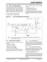
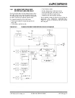
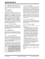
A typical incremental (a.k.a. optical) encoder has three
outputs: Phase A, Phase B, and an index pulse. These
signals are useful and often required in position and
speed control of ACIM and SR motors.
The two channels, Phase A (QEA) and Phase B (QEB),
have a unique relationship. If Phase A leads Phase B,
then the direction (of the motor) is deemed positive or
forward. If Phase A lags Phase B, then the direction (of
the motor) is deemed negative or reverse.
A third channel, termed index pulse, occurs once per
revolution and is used as a reference to establish an
absolute position. The index pulse coincides with
Phase A and Phase B, both low.
14.2
16-bit Up/Down Position Counter
Mode
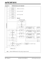
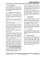
The 16-bit Up/Down Counter counts up or down on
every count pulse, which is generated by the difference
of the Phase A and Phase B input signals. The counter
acts as an integrator, whose count value is proportional
to position. The direction of the count is determined by
the UPDN signal, which is generated by the
Quadrature Encoder Interface Logic.
14.2.1
POSITION COUNTER ERROR
CHECKING
Position count error checking in the QEI is provided for
and indicated by the CNTERR bit (QEICON<15>). The
error checking only applies when the position counter
is configured for Reset on the Index Pulse modes
(QEIM<2:0> = ‘
110
’ or ‘
100
’). In these modes, the
contents of the POSCNT register is compared with the
values (0xFFFF or
1
, depending on direc-
tion). If these values are detected, an error condition is
generated by setting the CNTERR bit and a QEI count
error interrupt is generated. The QEI count error
interrupt can be disabled by setting the CEID bit
(DFLTCON<8>). The position counter continues to
count encoder edges after an error has been detected.
The POSCNT register continues to count up/down until
a natural rollover/underflow. No interrupt is generated
for the natural rollover/underflow event. The CNTERR
bit is a Read/Write bit and reset in software by the user.
14.2.2
POSITION COUNTER RESET
The Position Counter Reset Enable bit, POSRES
(QEI<2>) controls whether the position counter is reset
when the index pulse is detected. This bit is only
applicable when QEIM<2:0> = ‘
100
’ or ‘
110
’.
If the POSRES bit is set to ‘
1
’, then the position counter
is reset when the index pulse is detected. If the
POSRES bit is set to ‘
0
’, then the position counter is not
reset when the index pulse is detected. The position
counter will continue counting up or down, and will be
reset on the rollover or underflow condition.
The interrupt is still generated on the detection of the
index pulse and not on the position counter overflow/
underflow.
14.2.3
COUNT DIRECTION STATUS
As mentioned in the previous section, the QEI logic
generates an UPDN signal, based upon the relation-
ship between Phase A and Phase B. In addition to the
output pin, the state of this internal UPDN signal is sup-
plied to a SFR bit UPDN (QEICON<11>) as a read only
bit. To place the state of this signal on an I/O pin, the
SFR bit PCDOUT (QEICON<6>) must be 1.
14.3
Position Measurement Mode
There are two Measurement modes which are sup-
ported and are termed x2 and x4. These modes are
selected by the QEIM<2:0> mode select bits located in
SFR QEICON<10:8>.
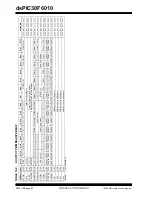
When control bits QEIM<2:0> =
100
or
101
, the x2
Measurement mode is selected and the QEI logic only
looks at the Phase A input for the position counter
increment rate. Every rising and falling edge of the
Phase A signal causes the position counter to be incre-
mented or decremented. The Phase B signal is still
utilized for the determination of the counter direction,
just as in the x4 mode.
Within the x2 Measurement mode, there are two
variations of how the position counter is reset:
1.
Position counter reset by detection of index
pulse, QEIM<2:0> =
100
.
2.
Position counter reset by match with MAXCNT,
QEIM<2:0> =
101
.
When control bits QEIM<2:0> =
110
or
111
, the x4
Measurement mode is selected and the QEI logic looks
at both edges of the Phase A and Phase B input sig-
nals. Every edge of both signals causes the position
counter to increment or decrement.
Within the x4 Measurement mode, there are two
variations of how the position counter is reset:
1.
Position counter reset by detection of index
pulse, QEIM<2:0> =
110
.
2.
Position counter reset by match with MAXCNT,
QEIM<2:0> =
111
.
The x4 Measurement mode provides for finer resolu-
tion data (more position counts) for determining motor
position.
Summary of Contents for dsPIC30F6010
Page 12: ...dsPIC30F6010 DS70119B page 10 Advance Information 2004 Microchip Technology Inc NOTES...
Page 32: ...dsPIC30F6010 DS70119B page 30 Advance Information 2004 Microchip Technology Inc NOTES...
Page 38: ...dsPIC30F6010 DS70119B page 36 Advance Information 2004 Microchip Technology Inc NOTES...
Page 50: ...dsPIC30F6010 DS70119B page 48 Advance Information 2004 Microchip Technology Inc NOTES...
Page 68: ...dsPIC30F6010 DS70119B page 66 Advance Information 2004 Microchip Technology Inc NOTES...
Page 72: ...dsPIC30F6010 DS70119B page 70 Advance Information 2004 Microchip Technology Inc NOTES...
Page 76: ...dsPIC30F6010 DS70119B page 74 Advance Information 2004 Microchip Technology Inc NOTES...
Page 86: ...dsPIC30F6010 DS70119B page 84 Advance Information 2004 Microchip Technology Inc NOTES...
Page 108: ...dsPIC30F6010 DS70119B page 106 Advance Information 2004 Microchip Technology Inc NOTES...
Page 116: ...dsPIC30F6010 DS70119B page 114 Advance Information 2004 Microchip Technology Inc NOTES...
Page 128: ...dsPIC30F6010 DS70119B page 126 Advance Information 2004 Microchip Technology Inc NOTES...
Page 150: ...dsPIC30F6010 DS70119B page 148 Advance Information 2004 Microchip Technology Inc NOTES...
Page 164: ...dsPIC30F6010 DS70119B page 162 Advance Information 2004 Microchip Technology Inc NOTES...
Page 208: ...dsPIC30F6010 DS70119B page 206 Advance Information 2004 Microchip Technology Inc NOTES...
Page 220: ...dsPIC30F6010 DS70119B page 220 Advance Information 2004 Microchip Technology Inc NOTES...
Page 221: ...2004 Microchip Technology Inc Advance Information DS70119B page 221 dsPIC30F6010 NOTES...

