Board Configuration
2015 Microchip Technology Inc.
DS50002403A-page 21
3.2.4.3.2
External PHY - Power
The Jumper (J26) is used to supply “on-board 5V or delayed 5V” to external PHY
Board.
3.2.4.3.3
External PHY - MII Link
Connect MII Link from an external PHY board (EVB-LAN8740) to the 1st pin of J24
through jumpers as shown in
3.2.4.3.4
External PHY - MII Reset
Connect reset from an external PHY board (EVB-LAN8740) to the 3rd pin of J24
through jumpers as shown in
3.2.4.3.5
External PHY - CLK
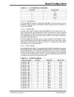
The MII_CLK25 from LAN9252 is available on J24-12th pin and this signal has to be
routed to Master Clock of the External PHY.
Remove on board crystal and connect MII-CLK25 from MII connector to the LAN8740
OSCO pin as shown below in
(through Green wire).
FIGURE 3-5:
LAN8740
TABLE 3-14:
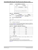
EXTERNAL PHY BOARD PIN SETTINGS
Header
Pin Settings
Description
J26
1-2
Connects on-board 5V to an external PHY Board (Default)
J26
2-3
Connects Delayed 5V to an external PHY Board in Enhanced
Link detection
Note:
The EVB-LAN8740 is used for an External PHY. Refer to link
http://ww1.microchip.com/downloads/en/DeviceDoc/evb8740_user.pdf
for
more details on EVB-LAN8740.

