Installation and Operation
2015 Microchip Technology Inc.
DS50002347A-page 17
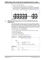
The headroom voltage is programmed to the desired level using
.
EQUATION 2-2:
THE DESIRED DC LEVEL OF HEADROOM VOLTAGE
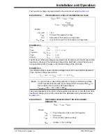
EXAMPLE 2-2:
The DC level of the bus voltage is regulated to be the total sum of the DC level of the
headroom voltage and the operating voltage of the LED load, and will thereby vary
during operation with changes in the forward voltage of the LED load.
EXAMPLE 2-3:
The power dissipation of the LED current regulator must be low, so the DC level of the
headroom voltage (V
HDC
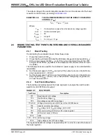
) will be minimized, the dissipation being calculated using
.
EQUATION 2-3:
THE POWER DISSIPATION OF THE LED CURRENT
REGULATOR
For:
V
HDC
=
7.5V
Then:
K
DIV
=
1.25/7.5 = 0.166
Therefore:
R
HVT
/R
HVB
=
5.0
Then:
R
HVB
=
10 k
Ω
Choose:
R
HVT
=
50 k
Ω
VREF, HVR VHDC KDIV
=
KDIV
RHVB
RHVB RHVT
+
---------------------------------------
=
Where:
V
REF,
HVR
=
1.25V
V
HDC
=
DC level of the headroom voltage
K
DIV
=
Attenuation of the headroom voltage divider
R
HVT,
R
HVB
=
Top and bottom resistor of the headroom voltage divider
If a 140 LED string is used, a forward voltage drop of 3V on each LED is assumed.
Then, the Bus Voltage level will be:
V
DC
= 140 × 3 + V
HDC
= 420 + 7.5 = 427.5V
DC
Note:
In order to have a good Valley detection, choose an LED string voltage
20-30V greater than the peak input voltage (which is usually 264V
AC
). In
this condition, the minimum LED load voltage is
V
LED MIN
= 20 + 1.41 × 264 = 392V
DC
PDIS ILED VHDC
=
Where:
P
DIS
=
Power dissipation of the current LED regulator
I
LED
=
LED current
V
HDC
=
DC level of the headroom voltage
P
DIS
=
0.090A × 7.5V= 0.675W

