HV9805 230V
AC
Off-Line LED Driver Evaluation Board User’s Guide
DS50002347A-page 16
2015 Microchip Technology Inc.
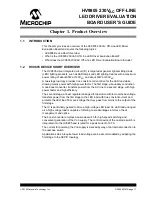
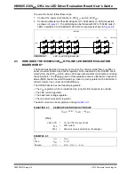
To power the board, follow these steps:
1. Connect the power at terminals J1, 230V
AC
~ and J2, 230V
AC
~.
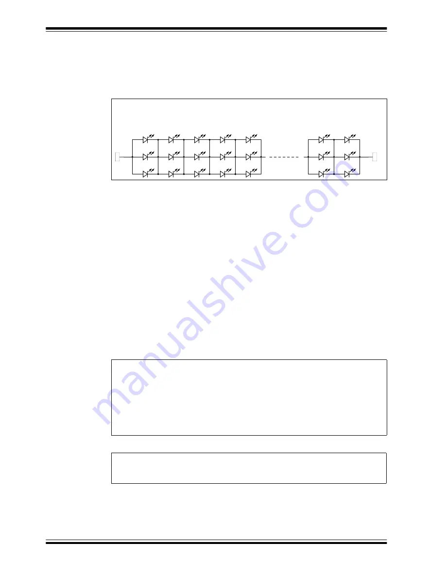
2. Connect a voltmeter and the LED string at J3 (V+ LED) and J4 (V- LED) connectors,
as shown in
. The LED string can be formed with 132 to 150 LED cells (3
LEDs in parallel), 80 mA SMD LED, 280 mW. An example is shown in
FIGURE 2-2:
LED Load String Example.
2.3
HOW DOES THE HV9805 230V
AC
OFF-LINE LED DRIVER EVALUATION
BOARD WORK?
The board was designed to supply, by means of a common-mode filter, a rectifier; a
boost converter followed by a linear regulator, both conducted by the HV9805 driver
directly from the 230V
AC
mains; and an LED load; with constant current also controlling
the power factor. The topology used in this evaluation board is a Boundary Conduction
Mode (BCM) boost converter followed by a linear current regulator on the LED side in
order to assure true current and high efficiency.
The HV9805 device has the following regulators:
• The V
DD
regulator, which is inside the chip (only the filter capacitor is outside)
• The LED current regulator
• The headroom voltage regulator
• The line current waveform regulator
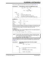
The LED current can be programmed using
EQUATION 2-1:
SENSE RESISTORS RELATIONSHIP
EXAMPLE 2-1:
2853
1
LED +
2853
2853
2853
2853
1
LED -
LED LOAD
1
2
3
4
5 ----------------------------------
149
150
LED cells
If:
I
LED
=
90 mA
Then:
R
CRS
=
11.11
Ω
Choose:
R11A
=
R11B = 22
Ω
= 2 × R
CRS
VREF, CCR ILED RCRS
=
Where:
V
REF
, CCR
=
1.0V (at 100% current level)
I
LED
=
LED current
R
CRS
=
Resistor's value is selected by the designer

