background image

MCP1643 SYNCHRONOUS BOOST LED

CONSTANT CURRENT REGULATOR

EVALUATION BOARD USER’S GUIDE

 2013 Microchip Technology Inc.

DS20005196A-page 13

Chapter 2.  Installation and Operation

2.1

INTRODUCTION

The


MCP1643 has been developed for applications that require driving an LED from a 

low-voltage source. The Microchip low-voltage technology allows the device to start up 
from a low 0.65V input voltage without output overshoot. At the same time, the device 
is capable of achieving high efficiency by integrating the low resistance N-Channel 
Boost switch and the synchronous P-Channel switch and by using a low voltage refer-
ence (0.120V) to reduce the power dissipation on the sensing resistor. Another import-
ant feature is that the device integrates the compensation and protection circuitry, so 
that the final solution will require a minimum number of additional components. 
When disabled using the EN switch, the true disconnect option removes the normal 
boost topology path from input to output. 


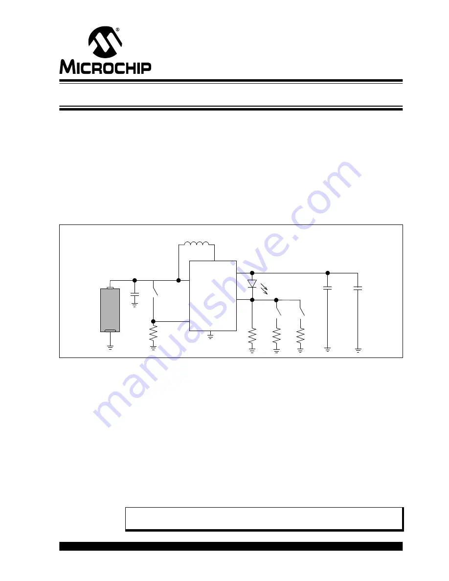
FIGURE 2-1:

Synchronous Boost 25, 50, 75, 100 mA Constant Current Application.

2.1.1

MCP1643 Evaluation Board Features

The MCP1643 Synchronous Boost LED Constant Current Regulator Evaluation Board 
has the following features:
• It can be powered by one-cell Alkaline, NiCd, or NiMH batteries, or by external 

power supply

• Input voltage range, V

IN

: 0.5V to 2.5V, with V

IN 



V

OUT

, after start-up

• Start-up voltage: 0.65V 
• Fixed output current: 25 mA, 50 mA, 75 mA or 100 mA, selected using a mini-dip 

switch on board

• PWM Switching Frequency: 1 MHz
• Enable state selectable using mini-dip switch on board
• 1.6A Peak Input Current Limit
• Overtemperature Protection (if the die temperature exceeds 150°C, 25°C hysteresis)
• Mechanical battery reverse polarity protection


V

IN

GND

V

FB

C

OUT

2 X 10 µF

C

IN

10 µF

L

1

4.7 µH

SW

LED


4.7

EN

V

OUT

+

-

AL

KA

L

IN

E

MCP1643

R

SET0

4.7

R

SET1

2.4

R

SET2

EN

REN

1M

Note:

For V

IN

 < V

OUT

, I

LED

 remains in regulation up to V

IN

 = V

LED 

@ LED typical 

V

F

 and I

F.


Summary of Contents for MCP1643

Page 1: ...2013 Microchip Technology Inc DS20005196A MCP1643 Synchronous Boost LED Constant Current Regulator Evaluation Board User s Guide...

Page 2: ...protection feature may be a violation of the Digital Millennium Copyright Act If such acts allow unauthorized access to your software or other copyrighted work you may have a right to sue for relief u...

Page 3: ...2013 Microchip Technology Inc DS20005196A page 3 Object of Declaration MCP1643 Synchronous Boost LED Constant Current Regulator Evaluation Board User s Guide...

Page 4: ...MCP1643 Synchronous Boost LED Constant Current Regulator Evaluation Board User s Guide DS20005196A page 4 2013 Microchip Technology Inc NOTES...

Page 5: ...erview 1 1 Introduction 11 1 2 MCP1643 Short Overview 11 1 3 What is the MCP1643 Synchronous Boost LED Constant Current Regulator Evaluation Board 12 1 4 MCP1643 Synchronous Boost LED Constant Current...

Page 6: ...MCP1643 Synchronous Boost LED Constant Current Regulator Evaluation Board User s Guide DS20005196A page 6 2013 Microchip Technology Inc NOTES...

Page 7: ...egulator Evaluation Board and a description of the user s guide Appendix A Schematic and Layouts Shows the schematic and layout diagrams for the MCP1643 Synchronous Boost LED Constant Current Regulato...

Page 8: ...A menu path File Save Bold characters A dialog button Click OK A tab Click the Power tab N Rnnnn A number in verilog format where N is the total number of digits R is the radix and n is a digit 4 b001...

Page 9: ...gn resources user s guides and hardware support documents latest software releases and archived software General Technical Support Frequently Asked Questions FAQs technical support requests online dis...

Page 10: ...MCP1643 Synchronous Boost LED Constant Current Regulator Evaluation Board User s Guide DS20005196A page 10 2013 Microchip Technology Inc NOTES...

Page 11: ...ith a minimum number of external components for applications powered by one cell two cell Alkaline NiCd or NiMH batteries The MCP1643 is a PWM only device that operates at a fixed 1 MHz switching freq...

Page 12: ...reduce the product design cycle time Four output currents can be selected 25 50 75 and 100mA The output current can be changed with a dual switch that changes the external LED current sense equivalent...

Page 13: ...mponents When disabled using the EN switch the true disconnect option removes the normal boost topology path from input to output FIGURE 2 1 Synchronous Boost 25 50 75 100 mA Constant Current Applicat...

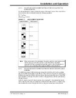
Page 14: ...the device The package selected for the MCP1643 Synchronous Boost LED Constant Current Regulator Evaluation Board is the MSOP 8 SW1 is the Enable switch which gives the state of the converter ON or OF...

Page 15: ...typical By varying the duty cycle of the PWM signal applied on EN input the LED current is changing linearly and the light intensity changes as well A 0 R1 resistor is used for bench testing By remov...

Page 16: ...MCP1643 Synchronous Boost LED Constant Current Regulator Evaluation Board User s Guide DS20005196A page 16 2013 Microchip Technology Inc NOTES...

Page 17: ...echnology Inc DS20005196A page 17 Appendix A Schematic and Layouts A 1 INTRODUCTION This appendix contains the following schematics and layouts for the MCP1643 Synchronous Boost LED Constant Current R...

Page 18: ...nology Inc A 2 BOARD SCHEMATIC VIN 8 SW 5 VOUT 4 NC 3 EN 1 7 VFB 2 PGND 6 U1 MCP1643 MSOP 8 GND SW_SMD_DIP SW2A SW2B 1 2 LD1 J3 J4 1 J1 1 J2 J5 J6 SW1 2 4 R4 10uF C1 10uF C2 DNP 10uF 0805 C3 0 R1 4 7u...

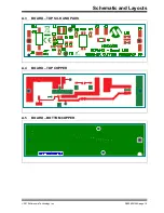
Page 19: ...Schematic and Layouts 2013 Microchip Technology Inc DS20005196A page 19 A 3 BOARD TOP SILK AND PADS A 4 BOARD TOP COPPER A 5 BOARD BOTTOM COPPER...

Page 20: ...MCP1643 Synchronous Boost LED Constant Current Regulator Evaluation Board User s Guide DS20005196A page 20 2013 Microchip Technology Inc NOTES...

Page 21: ...Inc MLEAWT A1 R250 0004E5 1 R1 Resistor 1206 0R0 Welwyn Components WCR1206 R005JI 3 R4 Resistor 0805 2R4 5 0 125W Panasonic ECG ERJ 6RQF2R4V 1 R6 Resistor 1M Ohm 1 10W 1 0603 SMD Panasonic ECG ERJ 3E...

Page 22: ...Tel 86 21 5407 5533 Fax 86 21 5407 5066 China Shenyang Tel 86 24 2334 2829 Fax 86 24 2334 2393 China Shenzhen Tel 86 755 8864 2200 Fax 86 755 8203 1760 China Wuhan Tel 86 27 5980 5300 Fax 86 27 5980 5...

Page 23: ...Mouser Electronics Authorized Distributor Click to View Pricing Inventory Delivery Lifecycle Information Microchip ADM00435...

Reviews: