Hardware Description
2014 Microchip Technology Inc.
DS50002240A-page 17
3.1
INPUT AND ANALOG FRONT END
The MCP39F501 Power Monitor Demonstration Board comes populated with
components designed for 220V line voltage. However, it will work from 90V to 230V. At
the bottom of the main board, there are the high-voltage line and neutral connections.
There are four connections from the PCB to the meter casing. They are labeled LINE,
NEUTRAL, SHUNT1 and SHUNT2. The shunt sits on the high- or line-side of a
two-wire system and the meter employs a hot or “live” ground. The wires going into the
shunt to SHUNT1 and SHUNT2 should be twisted together. The wires going into the
LINE and NEUTRAL side of the meter should be twisted together, and also kept away
from the SHUNT1 and SHUNT2 wires, if possible.
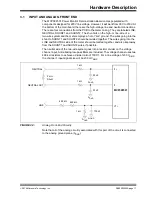
The neutral side of the two-wire system goes into a resistor divider on the voltage
channel input. Anti-aliasing low-pass filters are included. The voltage channel uses two
499 k
resistors to achieve a divider ratio of 1000:1. For a line voltage of 230 V
RMS
,
the channel 1 input signal size will be 230 mV
RMS
.
FIGURE 3-3:
Analog Front-End Circuitry.
Note that all of the analog circuitry associated with this part of the circuit is connected
to the analog ground plane (A
GND
).
499 k
LINE
499 k
1 k
100 nF
A
GND
A
GND
V1+
1 k
NEUTRAL
33 nF
A
GND
I1+
1 k
NEUTRAL OUT
33 nF
A
GND
I1-
2 m
Shunt
MCP39F501


