MCP8063 12V 3-Phase BLDC Sensorless Fan Controller Demonstration Board Kit User’s Guide
DS50002248B-page 18
2014 - 2015 Microchip Technology Inc.
2.1.2
Board Installation
identifies the required points for using the MCP8063 12V 3-Phase BLDC
Sensorless Fan Controller Demonstration Board.
FIGURE 2-6:
Top View - Hardware Components.
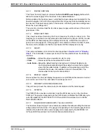
To use the MCP8063 12V 3-Phase BLDC Sensorless Fan Controller Demonstration
Board Kit, these steps should be followed:
1. Plug in the MCP8063 Daughter Board on its socket (see
).
2. To plug in a 3-phase BLDC sensorless fan, use the MCP8063 Daughter Board fan
connector. Note that the connection can be done in normal or reverse mode. If the
fan rotates in reverse mode, the connector can be flipped to rotate in normal mode.
3. Start the MCP8063 12V 3-Phase BLDC Sensorless Fan Controller
Demonstration Board software.
4. Plug the mini-USB cable from the USB port of a computer to the MCP8063 12V
3-Phase BLDC Sensorless Fan Controller Demonstration Board connector. The
LED indicating a ON state will light up.
5. If required, let the computer identify the MCP8063 12V 3-Phase BLDC
Sensorless Fan Controller Demonstration Board. Once the USB connection is
ready, the USB LED will light up
and remain on for as long as the USB connection
is active.
6. Restart the computer, if required.
7. Connect the power supply to the V
IN
test point. The V
IN
value is 18V ±10%. The
power supply should be able to deliver up to 1.0A. The GUI should report the V
IN
value of the board.
18V V
IN
+
-
Mini-USB
USB
PWR
ON
LED
LED
LED
connector
Daughter board
fan connector
ADM00532 with Daughter Board
D
a
1
6
3
4
5
Daughter board socket
18V V
IN
+
-
Mini-USB
USB
PWR
ON
LED
LED
LED
connector
ADM00532 w/o Daughter Board
Legend:
1 = Power input connector (16V to 20V)
4 = ON, PWR (fan driver powered) and USB status
LED indicators
2 = Daughter board socket
5 = Mini-USB connector
3 = Daughter board fan connector
6 = Plugged daughter board
1
4
2
5
Daughter board socket
18V V
IN
+
-
Mini-USB
USB
PWR
ON
LED
LED
LED
connector
ADM00532 w/o Daughter Board
1
4
2
5
Note:
The order of these steps is provided as an example and can be changed.
Summary of Contents for MCP8063
Page 27: ...2014 2015 Microchip Technology Inc DS50002248B page 27 A 3 BOARD TOP SILK...
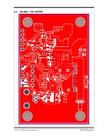
Page 29: ...2014 2015 Microchip Technology Inc DS50002248B page 29 A 5 BOARD TOP COPPER...
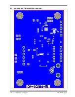
Page 31: ...2014 2015 Microchip Technology Inc DS50002248B page 31 A 7 BOARD BOTTOM COPPER AND SILK...
Page 39: ...2014 2015 Microchip Technology Inc DS50002248B page 39 NOTES...

