Fabric DDR Subsystem
Microsemi ProprietaryUG0446 User Guide Revision 7.0
204
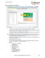
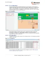
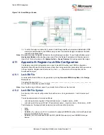
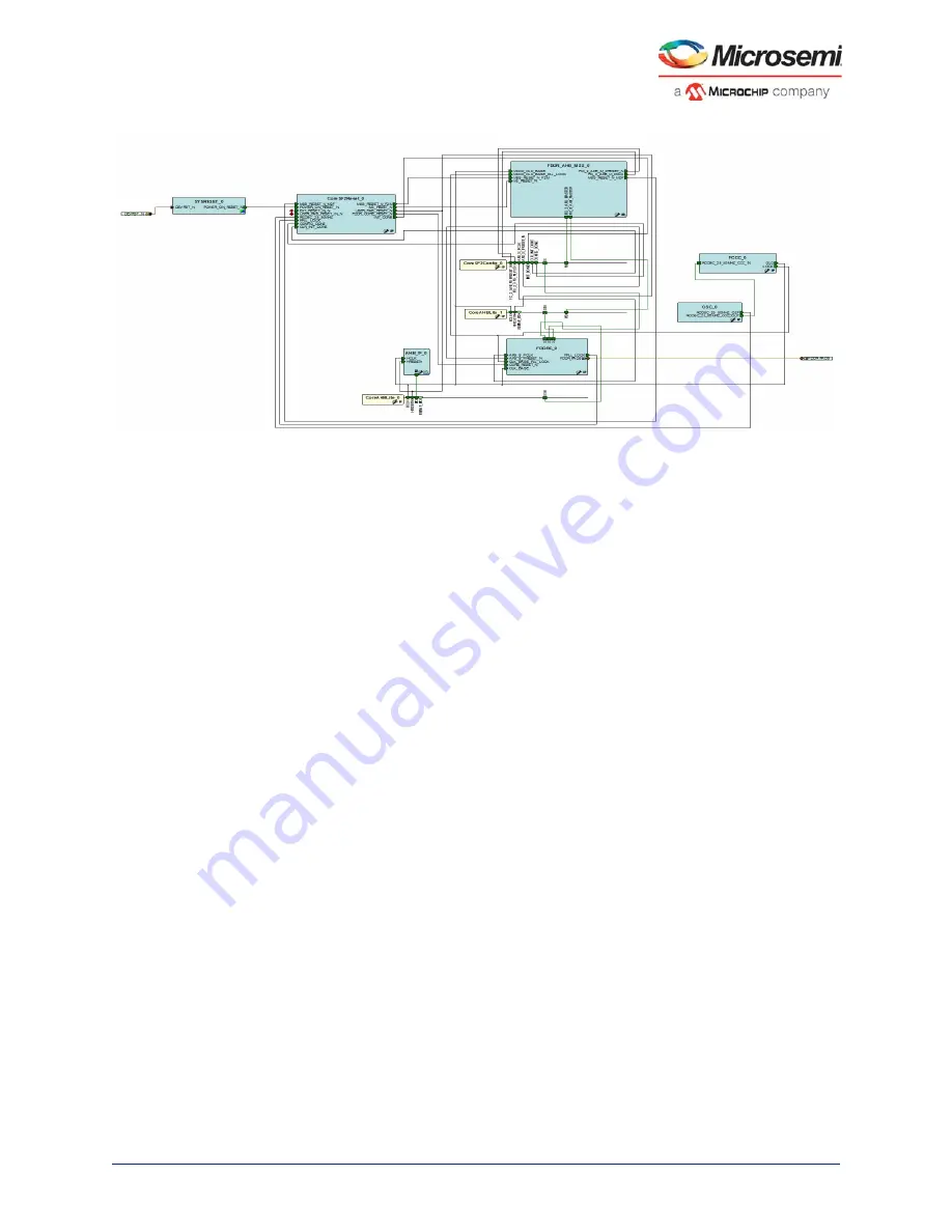
Figure 124 •
SmartDesign Canvas
14. To verify the design in Libero SoC, create a SmartDesign testbench project and instantiate a DDR
memory model provided by the DDR memory vendor. Simulate the design and observe the AHB
read and write transactions.
Note:
Microsemi provides the System Builder tool to simplify design creation. To use System Builder, select
Use System Builder
while creating a new project from the Design Templates and Creators panel in
Libero SoC. Follow the steps in the
System builder - Device Features
GUI and generate the design.
4.11
Appendix B: Register Lock Bits Configuration
The Register Lock Bits Configuration tool is used to lock MSS, SerDes, and FDDR configuration
registers of SmartFusion2 devices to prevent them from being overwritten by masters that have access
to these registers. Register lock bits are set in a text (
*.txt
) file, which is then imported into the
SmartFusion2 project.
4.11.1
Lock Bit File
An initial, default lock bit file can be generated by clicking
Generate FPGA Array Data
in the
Design
Flow
window.
The default file located at
<proj_location>/designer/<root>/<root>_init_config_lock_bits.txt
can be used to make the required changes.
Note:
Save the file using a different name if you modify the text file to set the lock bits.
4.11.2
Lock Bit File Syntax
A valid entry in the lock bit configuration file is defined as a <lock_parameters> < lock bit value> pair
format.
The lock parameters are structured as follows:
•
Lock bits syntax for a register: <Physical block name>_<register name>_LOCK
•
Lock bits syntax for a specific field: <Physical block name>_<register name>_<field name>_LOCK
The following are the physical block names (varies with device family and die):
•
MSS
•
FDDR
•
SERDES_IF_x (where x is 0,1,2,3 to indicate the physical SERDES location) for SmartFusion2 and
IGLOO2 (010/025/050/150) devices
•
SERDES_IF2 for SmartFusion2 and IGLOO2 (060/090) devices (only one SERDES block per
device)

