MPLAB STARTER KIT FOR PIC18F
USER’S GUIDE
©
2009 Microchip Technology Inc.
DS51852A-page 33
Appendix B. USB Current Draw Requirements
This chapter describes the key USB specification current limits and provides a func-
tional overview of the soft start circuitry used by the MPLAB Starter Kit for PIC18F to
meet them. The appendix includes the following sections:
• USB Current Specifications
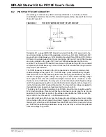
• PIC18F Starter Kit Soft Start Circuitry
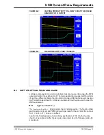
• Soft Start Functions and Usage
• Suspend Current Limitations with the Starter Kit
B.1
USB CURRENT SPECIFICATIONS
There are three major USB current specifications that the soft start circuitry addresses:
inrush current during initial plug in, total application current draw, and suspend current
limitations.
B.1.1
Inrush Current
All USB devices are required to limit their inrush draw from the bus such that there is a
capacitance change of no more than 10
μ
F for the device. (Since the USB is a 5V bus,
this equates to a charge inrush of 50
μ
C.) Some applications, like the OLED on the
starter kit, may cause a capacitance change of greater than 10
μ
F. To meet the
specification, the application can use current management techniques to limit the
inrush current and spread the charge over a longer period of time.
B.1.2
Total Application Current Draw
USB devices are limited to 100 mA of total current draw during the enumeration phase.
The enumeration phase is the time during which the device is first attached to the bus
and when the host sends a
SET_CONFIGURATION
command to the device. Devices
may request for additional current by changing the
bMaxPower
parameter of the
configuration descriptor. The configuration descriptor can be found in the file,
usb_descriptors.c
, in each of the example demos. More information about the
bMaxPower
parameter and the configuration descriptor, in general, can be found in
Table 9-10 of the USB specification.
B.1.3
Suspend Current Limitations
When the USB bus is in Suspend mode, all attached USB devices are required to use
less than 2.5 mA of current draw from the bus. For applications that have features that
require more current than is allowed, there are several options available. The first is to
be a self-powered device and only draw current from the power supply. The second is
to implement a software controlled method for reducing the current to below the 2.5 mA
limit.
Summary of Contents for MPLAB
Page 1: ...2009 Microchip Technology Inc DS51852A MPLAB Starter Kit for PIC18F User s Guide...
Page 4: ...MPLAB Starter Kit for PIC18F User s Guide DS51852A page iv 2009 Microchip Technology Inc NOTES...
Page 10: ...MPLAB Starter Kit for PIC18F User s Guide DS51852A page 6 2009 Microchip Technology Inc NOTES...
Page 32: ...MPLAB Starter Kit for PIC18F User s Guide DS51852A page 28 2009 Microchip Technology Inc NOTES...
Page 42: ...MPLAB Starter Kit for PIC18F User s Guide DS51852A page 38 2009 Microchip Technology Inc NOTES...
Page 45: ...Index 2009 Microchip Technology Inc DS51852A page 41 NOTES...

