background image

MRF24WN0MA/MB

DS50002410A-page 22

Advance Information

 2015 Microchip Technology Inc.

4.1.2

RF EXPOSURE

All transmitters regulated by FCC must comply with RF
exposure requirements. KDB 447498 General RF
Exposure Guidance provides guidance in determining
whether proposed or existing transmitting facilities,
operations or devices comply with limits for human
exposure to Radio Frequency (RF) fields adopted by
the Federal Communications Commission (FCC).
This module is approved for installation into mobile
and/or portable host platforms and must not be co-
located or operating in conjunction with any other
antenna or transmitter except in accordance with FCC
multitransmitter guidelines. End users must be pro-
vided with transmitter operating conditions for satisfy-
ing RF Exposure compliance.

4.1.3

APPROVED EXTERNAL ANTENNA 
TYPES

To maintain modular approval in the United States, only
the antenna types that have been tested shall be used.
It is permissible to use different antenna manufacturers
provided the same antenna type that has similar inband
and out-of-band radiation patterns and antenna gain
(equal to or less than) is used.
Modular approval testing of the MRF24WN0MA/MB
module was performed with the antenna types listed in

Table 3-1

.

4.1.4

HELPFUL WEB SITES

Federal Communications Commission (FCC): 

http://www.fcc.gov

FCC Office of Engineering and Technology (OET) Lab-
oratory Division Knowledge Database (KDB): 

http://apps.fcc.gov/oetcf/kdb/index.cfm 

4.2

Canada

The MRF24WN0MA/MB module has been certified for
use in Canada under Industry Canada (IC) Radio Stan-
dards Specification (RSS) RSS-210 and RSSGen.
Modular approval permits the installation of a module in
a host device without the need to recertify the device.

4.2.1

LABELING AND USER 
INFORMATION REQUIREMENTS

Labeling Requirements for the Host Device (from Sec-
tion 3.2.1, RSS-Gen, Issue 3, December 2010): The
host device shall be properly labeled to identify the
module within the host device.
The Industry Canada certification label of a module
shall be clearly visible at all times when installed in the
host device, otherwise the host device must be labeled
to display the Industry Canada certification number of

the module, preceded by the words “Contains transmit-
ter module”, or the word “Contains”, or similar wording
expressing the same meaning, as follows: 

User Manual Notice for License-Exempt Radio Appara-
tus (from Section 7.1.3 RSS-Gen, Issue 3, December
2010): User manuals for license-exempt radio appara-
tus shall contain the following or equivalent notice in a
conspicuous location in the user manual or alterna-
tively on the device or both:

Transmitter Antenna (from Section 7.1.2 RSS-Gen,
Issue 3, December 2010): User manuals for transmit-
ters shall display the following notice in a conspicuous
location:

The above notice may be affixed to the device instead
of displayed in the user manual.

4.2.2

RF EXPOSURE

All transmitters regulated by IC must comply with RF
exposure requirements listed in RSS-102 - Radio Fre-
quency (RF) Exposure Compliance of Radiocommuni-
cation Apparatus (All Frequency Bands). 

Contains transmitter module IC: 7693A-24WN0

This device complies with Industry Canada license-
exempt RSS standard(s). Operation is subject to the 
following two conditions: (1) this device may not 
cause interference, and (2) this device must accept 
any interference, including interference that may 
cause undesired operation of the device.

Le présent appareil est conforme aux CNR d'Indus-
trie Canada applicables aux appareils radio exempts 
de licence. L'exploitation est autorisée aux deux con-
ditions suivantes: (1) l'appareil ne doit pas produire 
de brouillage, et (2) l'utilisateur de l'appareil doit 
accepter tout brouillage radioélectrique subi, même 
si le brouillage est susceptible d'en compromettre le 
fonctionnement.

Under Industry Canada regulations, this radio trans-
mitter may only operate using an antenna of a type 
and maximum (or lesser) gain approved for the trans-
mitter by Industry Canada. To reduce potential radio 
interference to other users, the antenna type and its 
gain should be so chosen that the equivalent isotrop-
ically radiated power (e.i.r.p.) is not more than that 
necessary for successful communication.

Conformément à la réglementation d'Industrie Can-
ada, le présent émetteur radio peut fonctionner avec 
une antenne d'un type et d'un gain maximal (ou 
inférieur) approuvé pour l'émetteur par Industrie Can-
ada. Dans le but de réduire les risques de brouillage 
radioélectrique à l'intention des autres utilisateurs, il 
faut choisir le type d'antenne et son gain de sorte 
que la puissance isotrope rayonnée équivalente 
(p.i.r.e.) ne dépasse pas l'intensité nécessaire à 
l'établissement d'une communication satisfaisante.

Summary of Contents for MRF24WN0MA

Page 1: ...and reliable PCB mounting Environmentally Friendly RoHS Compliant Operational Single Operating Voltage 3 15V to 3 45V 3 3V typical Temperature Range 40 C to 85 C Industrial Low Current Consumption RX...

Page 2: ...most up to date version of this data sheet please register at our Worldwide Web site at http www microchip com You can determine the version of a data sheet by examining its literature number found on...

Page 3: ...tation tab The MRF24WN0MA module is approved for use with the integrated PCB trace antenna The MRF24WN0MB module is approved for use with specific external antenna types that are certified with the mo...

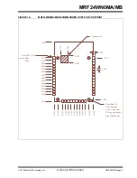
Page 4: ...m Table 1 2 describes the MRF24WN0MA MB pins FIGURE 1 2 MRF24WN0MA MB PIN DIAGRAM 37 GND GND 1 TEST 2 GND 3 VDD 4 NC 5 NC 6 NC 7 NC 8 NC 9 NC 10 NC 11 NC 12 SPI_CLK 13 SPI_MISO 14 36 GND 35 VDD 34 GND...

Page 5: ...ERNATE DI Lowest Power State active low 20 SPI_INT DO SPI interrupt output active low 21 MODE0 DI Mode select 0 Connect to GND 2 22 SPI_MOSI DI SPI data input 23 SPI_CS MODE1 DI SPI Chip Select Mode s...

Page 6: ...gure 1 3 Figure 1 4 and Figure 1 5 show the physical dimensions and the mounting details of the module Figure 1 6 and Figure 1 7 show the recommended host PCB footprint and layout FIGURE 1 3 MRF24WN0M...

Page 7: ...2015 Microchip Technology Inc Advance Information DS50002410A page 7 MRF24WN0MA MB FIGURE 1 4 MRF24WN0MA MB MODULE PHYSICAL DIMENSIONS BOTTOM VIEW LPHQVLRQV DUH LQ LQFKHV...

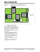
Page 8: ...icrochip Technology Inc FIGURE 1 5 MRF24WN0MA MB MODULE MOUNTING DETAILS Keep area around antenna approximately 1 25 inches clear of metallic structures for best performance 1 25 1 25 Edge of Host PCB...

Page 9: ...y Inc Advance Information DS50002410A page 9 MRF24WN0MA MB FIGURE 1 6 MRF24WN0MA MB RECOMMENDED HOST PCB FOOTPRINT URXQG 3ODQH RVW 3 GJH 6KLHOG 3DGV GLDPHWHU R QRW ORFDWH RVW 3 WRS OD HU FRSSHU XQGHU...

Page 10: ...lder reflow profiles To avoid damaging the module adhere to the following recommendations Solder reflow recommendations are provided in the Microchip Application Note AN233 Solder Reflow Recommendatio...

Page 11: ...to the Training Getting Started tab The MPLAB Harmony Help document is available for download from the MPLAB Harmony framework direc tory c microchip harmony version doc The PIC32 input output ports S...

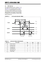
Page 12: ...on and wake up to ensure that the module start up in normal operation Once the module is operational the pin becomes the SPI Port Chip Select pin active low FIGURE 2 2 SPI SLAVE INTERFACE TIMING TABLE...

Page 13: ...recommended bypass capacitors The capacitors must be closely placed to the module 2 6 Hibernate The module enters the lowest power mode when the HIBERNATE pin is asserted low No state information is p...

Page 14: ...MRF24WN0MA MB DS50002410A page 14 Advance Information 2015 Microchip Technology Inc NOTES...

Page 15: ...matic Integral PCB Trace Antenna and Antenna Types 3 1 Application Schematic Figure 3 1 shows the schematic for the MRF24WN0MA module FIGURE 3 1 APPLICATION SCHEMATIC 9 9 9 9 9 5 N 5 N 5 N 8 05 1 0 1...

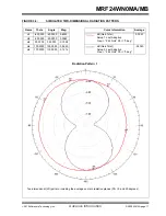
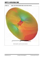
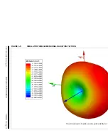
Page 16: ...B antenna Figure 3 2 illustrates the simulation drawing The two dimensional 2D radiation pattern is illustrated in Figure 3 3 whereas Figure 3 4 and Figure 3 5 shows the three dimensional 3D radiation...

Page 17: ...e m1 60 0000 60 0000 0 6323 dB Gain Total Setup 1 Last Adaptive Freq 2 44 GHz Phi 0 deg 0 0097 m2 20 0000 20 0000 0 3962 m3 30 0000 30 0000 0 1038 m4 100 0000 100 0000 0 9490 dB Gain Total Setup 2 Las...

Page 18: ...MRF24WN0MA MB DS50002410A page 18 Advance Information 2015 Microchip Technology Inc FIGURE 3 4 SIMULATED THREE DIMENSIONAL RADIATION PATTERN Radiation pattern against the module dimensions...

Page 19: ...2015 Microchip Technology Inc Advance Information DS50002410A page 19 FIGURE 3 5 SIMULATED THREE DIMENSIONAL RADIATION PATTERN Three dimensional 3D pattern and magnitude distribution...

Page 20: ...external antenna The choice of antenna is limited to the antenna types in which the module is tested and approved For a list of tested and approved antenna types that may be used with the module refe...

Page 21: ...ts own FCC ID number and if the FCC ID is not visible when the module is installed inside another device then the outside of the finished product into which the module is installed must also display a...

Page 22: ...or the word Contains or similar wording expressing the same meaning as follows User Manual Notice for License Exempt Radio Appara tus from Section 7 1 3 RSS Gen Issue 3 December 2010 User manuals for...

Page 23: ...h and Safety Article 3 1 a Electromagnetic Compatibility EMC Article 3 1 b and Radio Article 3 2 and are summarized in Table 3 1 European Com pliance Testing A Notified Body Opinion has also been issu...

Page 24: ...3 1 4 4 2 HELPFUL WEB SITES The Australian Communications and Media Authority www acma gov au 4 5 New Zealand The New Zealand radio regulations do not provide a modular approval policy similar to the...

Page 25: ...Internal Affairs and Communications MIC website The MRF24WN0MA MB module is labeled with its own technical conformity mark and certification number The final product in which this module is being used...

Page 26: ...chnology sales or distribution partners to obtain a Letter of Authority Integration of this module into a final product does not require additional radio certification provided installa tion instructi...

Page 27: ...specification is not implied Exposure above maximum rating conditions for extended periods may affect device reliability TABLE 5 2 RECOMMENDED OPERATING CONDITIONS Symbol Description Min Typ Max Units...

Page 28: ...2 412 2 472 GHz sRF Sensitivity CCK 1 Mbps 95 7 dBm 11 Mbps 87 7 OFDM 6 Mbps 92 7 54 Mbps 75 7 HT20 MCS0 92 7 MCS7 72 7 HT40 MCS0 90 7 MCS7 69 7 Note 1 Performance measured at J1 TABLE 5 6 RADIO TRAN...

Page 29: ...2015 Microchip Technology Inc Advance Information DS50002410A page 29 MRF24WN0MA MB APPENDIX A REVISION HISTORY Revision A August 2015 This is the initial released version of the document...

Page 30: ...MRF24WN0MA MB DS50002410A page 30 Advance Information 2015 Microchip Technology Inc NOTES...

Page 31: ...hip sales offices distributors and factory representatives CUSTOMER CHANGE NOTIFICATION SERVICE Microchip s customer notification service helps keep customers current on Microchip products Subscribers...

Page 32: ...MRF24WN0MA MB DS50002410A page 32 2015 Microchip Technology Inc NOTES...

Page 33: ...in information e g on pricing or delivery refer to the factory or the listed sales office PART NO I RM XXX Firmware Package Temperature Range Device Device MRF24WN0MA Integral Antenna MRF24WN0MB Exter...

Page 34: ...MRF24WN0MA MB DS50002410A page 34 Advance Information 2015 Microchip Technology Inc NOTES...

Page 35: ...red trademark of Microchip Technology Inc in other countries GestIC is a registered trademark of Microchip Technology Germany II GmbH Co KG a subsidiary of Microchip Technology Inc in other countries...

Page 36: ...86 24 2334 2829 Fax 86 24 2334 2393 China Shenzhen Tel 86 755 8864 2200 Fax 86 755 8203 1760 China Wuhan Tel 86 27 5980 5300 Fax 86 27 5980 5118 China Xian Tel 86 29 8833 7252 Fax 86 29 8833 7256 ASI...

Page 37: ...M W162M201E ISM43340 L77 TR BCM4352KMLG BCM43520KMLG BCM43217KMLG 7265 NGWWB W PPC WL KIT02 R11 RC CC2640 A M113DH3200PS3Q0 SX PCEAN2c WT 01S WT8266 S3 ESP 07S WT8266 S6 ESP 12S WT 01F WT8266 S5 ESP 1...

Reviews: